PicoScope 7 Automotive
Available for Windows, Mac, and Linux, the next evolution of our diagnostic scope software is now available.
Automotive guided tests
Library of examples on how to perform tests when using PicoScope.

Training
Our collection of training videos, articles, guides and information on training courses.

Waveform library
The Waveform Library is a global database of waveforms uploaded by PicoScope users.

Case studies
Real-life case studies show how the professionals use PicoScope to diagnose vehicle faults.

A to Z of PicoScope
Detailed description of various PicoScope software and hardware features.

Videos
Training resources and demonstrations on PicoScope and the Automotive Diagnostics Kit.

Newsletter
Archive of our monthly Automotive Newsletters.

Documentation
Download manuals, brochures, posters, and training materials.

Reviews and awards
Accolades for the preferred diagnostic tool for service centers and vehicle manufacturers.


10:1 Attenuator

20 A / 60 A DC (low amps) current clamp

Multimeter Probes
*At Pico we are always looking to improve our products. The tools used in this guided test may have been superseded and the products above are our latest versions used to diagnose the fault documented in this case study.
The purpose of this test is to examine the primary voltage and current on an external coil type ignition system.
WARNING
This test involves measuring a potentially hazardous voltage.
Please ensure you follow manufacturers' safety instructions and working practices and ensure the rated voltage for all accessories you are using meets or exceeds the expected voltage.

View connection guidance notes.
Note
The orientation of the current clamp relative to the wire will determine whether it has a positive or negative output. If a live waveform does not appear on your screen, or appears to be inverted, try reversing the orientation of the clamp.
If you are using a 20:1 attenuator please adjust the Probe settings for the relevant channel. These settings can be found under the Channel Options button, then: Probe > 20:1 Attenuator.
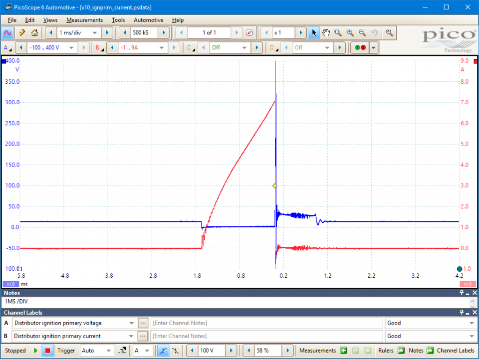
In the Non-current limiting waveform example Channel B shows a rise in primary current taking just over 5 ms and reaching around 5.5 amps maximum.
Channel A shows a primary voltage with good characteristics reaching a peak voltage which is over 300 volts.
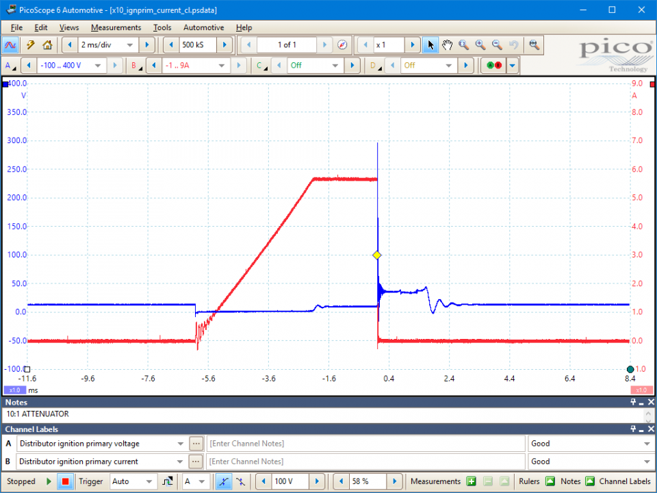
Your waveform may show a Current limiting system. In this waveform example on Channel B you can clearly see the peak current is limited by the ignition system. You will also see the current build time is much shorter.
Channel A once again shows a good primary voltage. In this waveform you will also see the characteristic jump in voltage at the point the system limits the current rise.
Note; values are system specific.
Go to the drop-down menu bar at the lower left corner of the Waveform Library window and select, Distributor ignition current or Distributor ignition voltage.

Technical Information
The primary ignition is so called as it forms the first part of the ignition circuit. Through the ignition coil, it drives the secondary High Tension (HT) output. The primary circuit has evolved from the basic contact breaker points and condenser to the distributorless and coil-per-cylinder systems in common use today. All of these ignition systems rely on the magnetic induction principle.
Magnetic Induction
This principle starts with a magnetic field being produced, as the coil's earth circuit is completed by either the contacts or the amplifier providing the coil negative terminal with a path to earth. When this circuit is complete, a magnetic field is produced and builds until the coil becomes magnetically saturated. At the predetermined point of ignition the coil earth is removed and the magnetic field collapses. As the field inside the coil 250 to 350 primary windings collapses it induces a voltage of 150 to 350 volts.
The induced voltage is determined by,
Dwell Period
Dwell is measured as an angle, with contact ignition, this is determined by the points gap. The definition of contact ignition dwell is the number of degrees of distributor rotation with the contacts closed.
As an example, a 4 cylinder engine has a dwell of approximately 45 degrees, which is 50% of one cylinder's complete primary cycle. The dwell period on an engine with electronic ignition is controlled by the current limiting circuit within the amplifier or control unit.
The dwell angle on a constant energy system expands as the engine speed increases, to compensate for a shorter period of rotation and maximise the strength of the magnetic field. The term constant energy refers to the available voltage produced by the coil. This remains constant regardless of engine speed, unlike contact ignition where an increase in engine speed means the contacts are closed for a shorter time and gives the coil less time to saturate .
The induced voltage on a variable dwell system remains constant regardless of engine speed, while it reduces on contact systems. This induced voltage can be seen on a primary waveform.
Both dwell periods will expand as the engine revs are increased. This is to maintain a constant coil saturation time, hence the term constant energy. If time rulers are placed at the beginning of the dwell period and on the induced voltage line the coil saturation time can be measured. This will remain exactly the same regardless of engine speed.
GT399
Disclaimer
This help topic is subject to changes without notification. The information within is carefully checked and considered to be correct. This information is an example of our investigations and findings and is not a definitive procedure.
Pico Technology accepts no responsibility for inaccuracies. Each vehicle may be different and require unique test
settings.
We know that our PicoScope users are clever and creative and we’d love to receive your ideas for improvement on this test. Click the Add comment button to leave your feedback.


