PicoScope 7 Automotive
Available for Windows, Mac, and Linux, the next evolution of our diagnostic scope software is now available.
Automotive guided tests
Library of examples on how to perform tests when using PicoScope.

Training
Our collection of training videos, articles, guides and information on training courses.

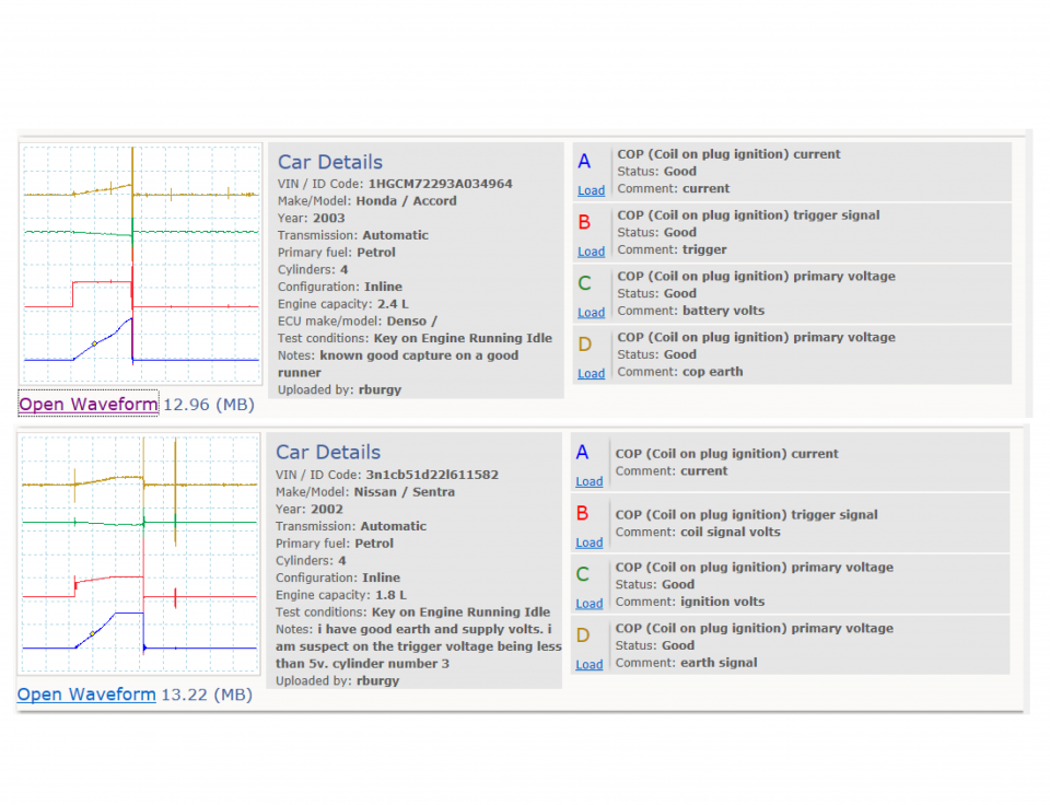
Waveform library
The Waveform Library is a global database of waveforms uploaded by PicoScope users.

Case studies
Real-life case studies show how the professionals use PicoScope to diagnose vehicle faults.

A to Z of PicoScope
Detailed description of various PicoScope software and hardware features.

Videos
Training resources and demonstrations on PicoScope and the Automotive Diagnostics Kit.

Newsletter
Archive of our monthly Automotive Newsletters.

Documentation
Download manuals, brochures, posters, and training materials.

Reviews and awards
Accolades for the preferred diagnostic tool for service centers and vehicle manufacturers.


20 A / 60 A DC (low amps) current clamp

Multimeter Probes
*At Pico we are always looking to improve our products. The tools used in this guided test may have been superseded and the products above are our latest versions used to diagnose the fault documented in this case study.
The purpose of this test is to examine the primary voltage and current within a 3 wire coil on plug unit.
WARNING
This test involves measuring a potentially hazardous voltage.
Please ensure you follow manufacturers' safety instructions and working practices and ensure the rated voltage for all accessories you are using meets or exceeds the expected voltage.
To avoid possible damage to your scope, you may need to use an attenuator for this test.
Scopes with a 200 V range, such as PicoScope 4x25 models, do not need an attenuator for this test.
All other PicoScope Automotive models need an attenuator on the channel input. You can use either a 10:1 or a 20:1 attenuator provided that you adjust the PicoScope software accordingly. Select from the appropriate Channel Options menu:
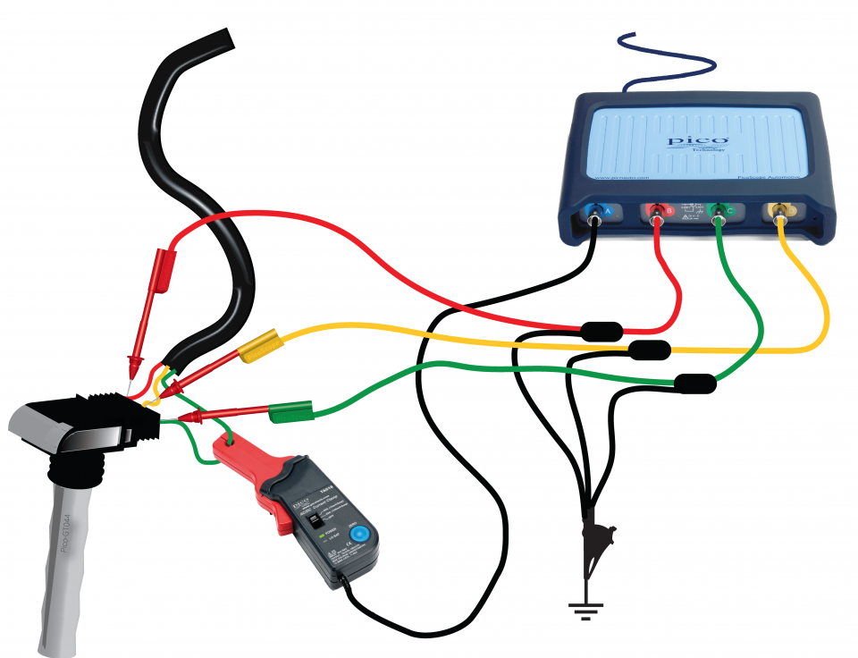
View connection guidance notes.
Note
The orientation of the current clamp relative to the wire will determine whether it has a positive or negative output. If a live waveform does not appear on your screen, or appears to be inverted, try reversing the orientation of the clamp.
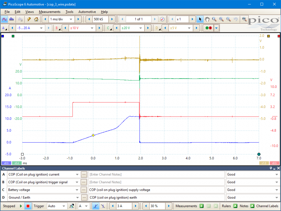
The example four-channel waveform, above, shows the current-limiting circuit in operation. The current switches on as the dwell period starts and rises until approximately 11 amps is reached in the primary circuit. At this point the current is maintained for a brief period of time and then released at the point of ignition. The length of time from the initial switching-on point to the moment the current is released depends on engine speed. The lower the engine speed, the shorter the current ramp; then the ramp lengthens with increasing engine revs.
The low-tension (LT) signal switches between zero volts and about 5 volts. When the trigger signal goes high, it causes the coil to switch on. As the voltage returns to zero, the current in the coil's primary winding switches off, the magnetic flux surrounding the winding collapses, this induces a voltage in the secondary and the coil's HT is fired.
The switch-on (zero rising to 5 volts) and switch-off (5 volts to zero) points are determined by the vehicle's Electronic Control Module (ECM). This interval between these events is called either the dwell period or the saturation time. The dwell period on an engine with electronic ignition is controlled by the current-limiting circuit in the amplifier or ECM. The time taken for the coil to reach saturation is about 3 milliseconds in our example.
The waveform being monitored is the supply voltage to the coil. The supply is at the battery or charging voltage of 12 volts or more. In the example waveform, the voltage is about 14.0 volts. When the coil's primary circuit is switched on, the voltage drops slightly, and as the current in the circuit increases to the target of 11 amps, the voltage drops accordingly. The final voltage is about 12 volts - 2 volts lower than the original voltage.
The voltage when the coil is disconnected is of course zero volts, rising to about 0.1 volts when the coil is energized. If the circuit is suffering from a poor earth connection, this voltage will be higher, so the lower the voltage, the better the earth connection.
Go to the drop-down menu bar at the lower left corner of the Waveform Library window and select, COP (Coil on plug ignition) primary voltage or COP (Coil on plug ignition) trigger signal.

The example waveform shows the current limiting circuit in operation. The current in the primary circuit switches on as the dwell period starts, and rises until a level of 11 amps is reached. This current is maintained until it is released at the moment of ignition.
As the engine speed increases, the dwell angle expands to maintain a constant coil saturation time and therefore constant energy. The coil saturation time can be measured by placing one time ruler at the beginning of the dwell period and the other at the end of the current ramp. The distance between the rulers will remain exactly the same regardless of engine speed.
The switch-on (zero rising to 5 volts) and switch-off (5 volts to zero) points of the coil are determined by the vehicle's Electronic Control Module (ECM). The time between these points is called either the dwell period or the coil's saturation time. The dwell period on an engine with electronic ignition is controlled by the current-limiting circuit in the amplifier or ECM.
Historically, the supply voltage was present as soon as the ignition switch was turned to the 'on' position. Modern systems, however, do not provide a supply until the key is turned to the 'crank' position and the engine turns. A simple fault such as a non-functioning crank angle sensor may result in a loss of supply voltage, simply because the electronic control circuits do not recognize that the engine is rotating.
The earth connection is essential to the operation of any electrical circuit in an engine. As the current increases, so does the voltage drop on any given electrical circuit. An earth return circuit can only be tested while the circuit is under load, so simple continuity testing to earth with a multimeter is inaccurate. As the coil's primary circuit is only complete during the dwell period, the voltage drop should be monitored during this period.
The voltage ramp on the earth signal should not exceed 0.5 volts. The flatter the waveform the better: a waveform with virtually no rise shows that the amplifier or module has a perfect earth. If the ramp is too high, the earth connections need to be investigated to identify the offending connection.
GT162-5
Disclaimer
This help topic is subject to changes without notification. The information within is carefully checked and considered to be correct. This information is an example of our investigations and findings and is not a definitive procedure.
Pico Technology accepts no responsibility for inaccuracies. Each vehicle may be different and require unique test
settings.
We know that our PicoScope users are clever and creative and we’d love to receive your ideas for improvement on this test. Click the Add comment button to leave your feedback.


