PicoScope 7 Automotive
Available for Windows, Mac, and Linux, the next evolution of our diagnostic scope software is now available.
Automotive guided tests
Library of examples on how to perform tests when using PicoScope.

Training
Our collection of training videos, articles, guides and information on training courses.

Waveform library
The Waveform Library is a global database of waveforms uploaded by PicoScope users.

Case studies
Real-life case studies show how the professionals use PicoScope to diagnose vehicle faults.

A to Z of PicoScope
Detailed description of various PicoScope software and hardware features.

Videos
Training resources and demonstrations on PicoScope and the Automotive Diagnostics Kit.

Newsletter
Archive of our monthly Automotive Newsletters.

Documentation
Download manuals, brochures, posters, and training materials.

Reviews and awards
Accolades for the preferred diagnostic tool for service centers and vehicle manufacturers.


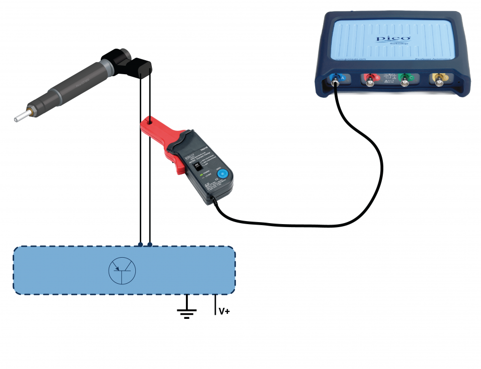
20 A / 60 A DC (low amps) current clamp
*At Pico we are always looking to improve our products. The tool used in this guided test may have been superseded and the product above is our latest version used to diagnose the fault documented in this case study.
The purpose of this test is to investigate piezo injector circuit current changes during idle, acceleration and overrun conditions.
WARNING
This test involves measuring a potentially hazardous voltage.
Please ensure you follow manufacturers' safety instructions and working practices and ensure the rated voltage for all accessories you are using meets or exceeds the expected voltage.
View connection guidance notes.
Notes
The orientation of the clamp relative to the wire will determine whether it has a positive or negative output. If a live waveform does not appear on your screen or appears to be inverted, try reversing the orientation of the clamp.
Engine at idle.
Engine with increased torque demand.

Engine at high speed.

Engine on overrun.
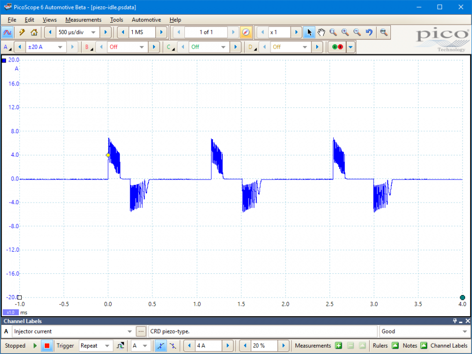
These known good waveforms have the following characteristics:
One or more pairs of positive and negative pulses, which respectively drive the opening and closing of the injector.
The pulses have peak amplitudes around ±7 A and cycle from 0 A to their peak value and back within 100 to 200 µs (the precise values will vary with system and test conditions).
Engine idle
3 x pairs of pulses, indicating two pilot injections and one main injection:
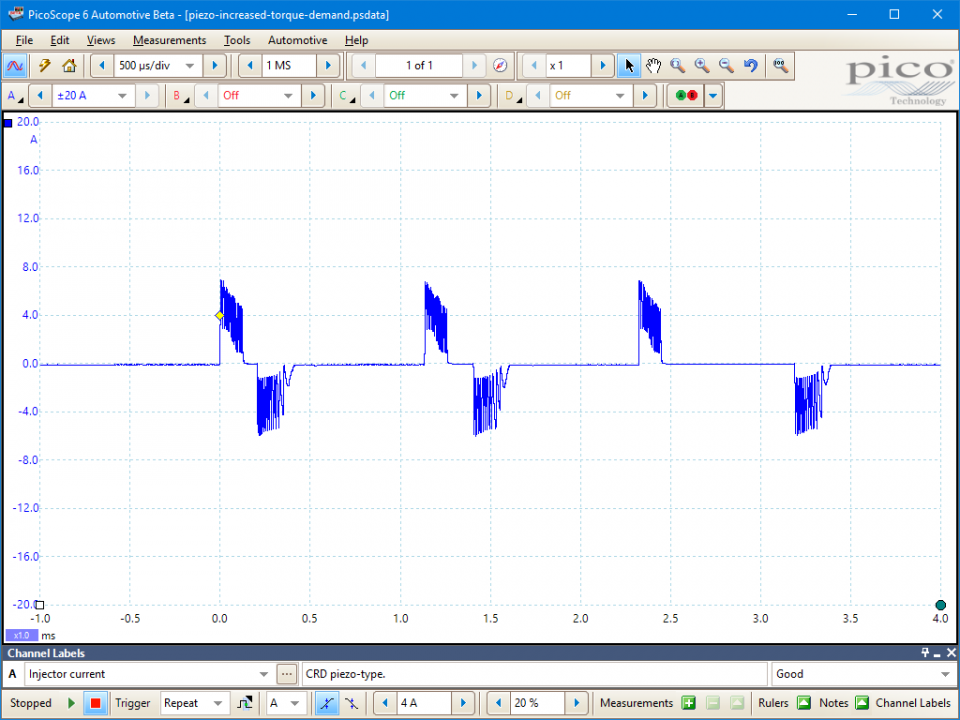
Increased torque demand
When the accelerator pedal is depressed and there is a demand for increased engine torque, the main injection duration increases to around 900 µs.
Fast idle speed
With the engine running at a higher speed, the pilot and main injection events all occur within a shorter total time period and their peak currents increase with increased alternator output at higher engine speeds.
Overrun
On engine overrun only the first pilot injection phase remains.
Go to the drop-down menu bar at the lower left corner of the Waveform Library window and select Injector current.


A piezoelectric diesel injector delivers atomized fuel directly to the engine combustion chamber when signaled to do so by the Engine Control Module (ECM). The injected fuel quantity is proportional to the injector duration (opening time), fuel rail pressure, fuel temperature and fluid viscosity.
Piezoelectric injectors operate faster than their solenoid-driven counterparts, which permits more injections per stroke, higher fuel pressures, and, therefore, more precise control of:
Piezoelectric injectors work using piezo crystal technology:
When a piezo crystal structure is compressed, it produces a voltage. Conversely when a voltage is applied to a piezo crystal, the crystal changes shape.
The piezoelectric injector uses these characteristics by applying a voltage across a stack of several hundred wafer-thin crystals. The result is a linear change in stack height, which causes a movement of the attached injector needle within the order of microseconds. Once the crystal structure has changed, the electrical current does not need to be maintained; the stack will hold its state until an electrical current is applied in the opposite direction.
Diesel injection quantities must be controlled very precisely for accurate emissions control. As such, every individually manufactured or reconditioned injector is tested after assembly and assigned a code that describes its exact injection characteristics. This code must be programmed into the ECM, using a scan tool, whenever an injector is fitted to the engine.
Diagnostically, it is recommended to check that the correct injector codes are assigned to the correct cylinders within the ECM if the engine has any misfire, poor performance or excessive emissions symptoms.
Typically, common rail diesel injectors are susceptible to mechanical and electrical faults, producing a variety of symptoms:
Selection of component-related Diagnostic Trouble Codes (DTCs):
U0105 Lost Communication With Fuel Injector Control Module
U0306 Software Incompatibility with Fuel Injector Control Module
U0406 Invalid Data Received From Fuel Injector Control Module
P0200 - Injector Control Circuit
P0201 - Injector 1 Control Circuit
P0202 - Injector 2 Control Circuit
P0203 - Injector 3 Control Circuit
P0204 - Injector 4 Control Circuit
P0205 - Injector 5 Control Circuit
P0206 - Injector 6 Control Circuit
P0207 - Injector 7 Control Circuit
P0208 - Injector 8 Control Circuit
P0209 - Injector 9 Control Circuit
P0210 - Injector 10 Control Circuit
P0211 - Injector 11 Control Circuit
P0212 - Injector 12 Control Circuit
P0261 - Cylinder 1 Injector Circuit Low
P0262 - Cylinder 1 Injector Circuit High
P0264 - Cylinder 2 Injector Circuit Low
P0265 - Cylinder 2 Injector Circuit High
P0267 - Cylinder 3 Injector Circuit Low
P0268 - Cylinder 3 Injector Circuit High
P0270 - Cylinder 4 Injector Circuit Low
P0271 - Cylinder 4 Injector Circuit High
P0273 - Cylinder 5 Injector Circuit Low
P0274 - Cylinder 5 Injector Circuit High
P0276 - Cylinder 6 Injector Circuit Low
P0277 - Cylinder 6 Injector Circuit High
P0279 - Cylinder 7 Injector Circuit Low
P0280 - Cylinder 7 Injector Circuit High
P0282 - Cylinder 8 Injector Circuit Low
P0283 - Cylinder 8 Injector Circuit High
P0285 - Cylinder 9 Injector Circuit Low
P0286 - Cylinder 9 Injector Circuit High
P0288 - Cylinder 10 Injector Circuit Low
P0289 - Cylinder 10 Injector Circuit High
P0291 - Cylinder 11 Injector Circuit Low
P0292 - Cylinder 11 Injector Circuit High
P0294 - Cylinder 12 Injector Circuit Low
P0295 - Cylinder 12 Injector Circuit High
GT098-EN
Disclaimer
This help topic is subject to changes without notification. The information within is carefully checked and considered to be correct. This information is an example of our investigations and findings and is not a definitive procedure.
Pico Technology accepts no responsibility for inaccuracies. Each vehicle may be different and require unique test
settings.
We know that our PicoScope users are clever and creative and we’d love to receive your ideas for improvement on this test. Click the Add comment button to leave your feedback.


