PicoScope 7 Automotive
Available for Windows, Mac, and Linux, the next evolution of our diagnostic scope software is now available.
Automotive guided tests
Library of examples on how to perform tests when using PicoScope.

Training
Our collection of training videos, articles, guides and information on training courses.

Waveform library
The Waveform Library is a global database of waveforms uploaded by PicoScope users.

Case studies
Real-life case studies show how the professionals use PicoScope to diagnose vehicle faults.

A to Z of PicoScope
Detailed description of various PicoScope software and hardware features.

Videos
Training resources and demonstrations on PicoScope and the Automotive Diagnostics Kit.

Newsletter
Archive of our monthly Automotive Newsletters.

Documentation
Download manuals, brochures, posters, and training materials.

Reviews and awards
Accolades for the preferred diagnostic tool for service centers and vehicle manufacturers.


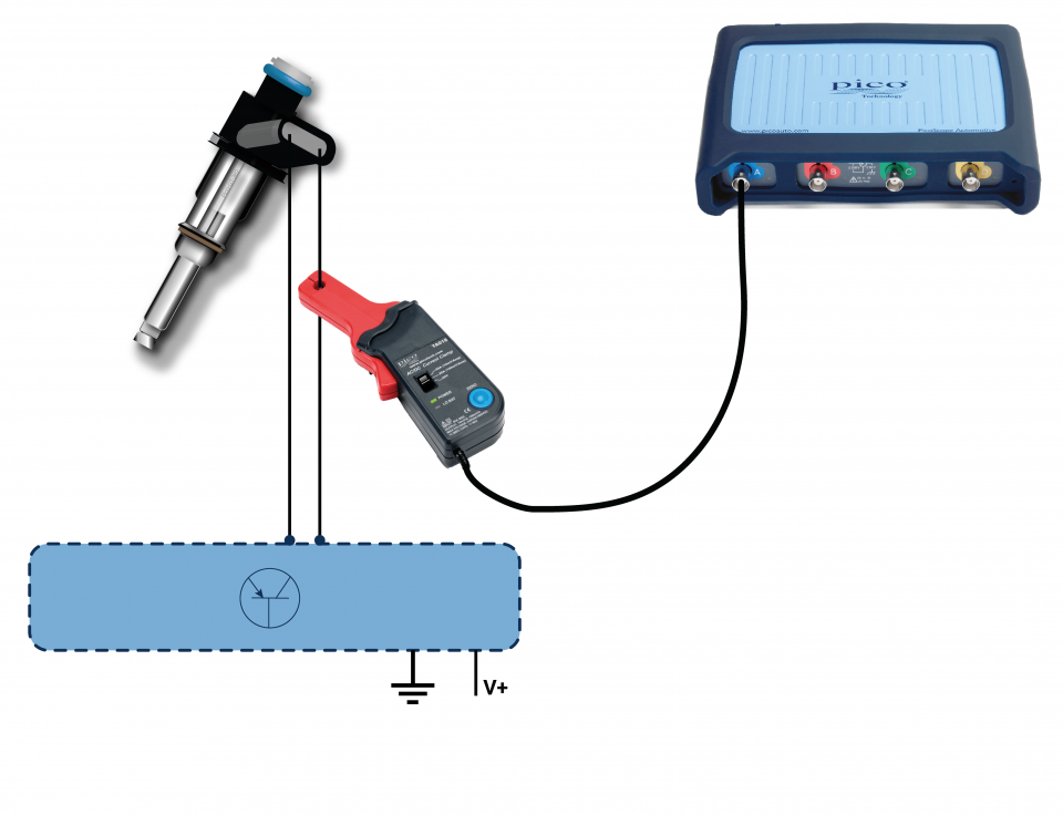
20 A / 60 A DC (low amps) current clamp

2 Pin AMP connector breakout lead
*At Pico we are always looking to improve our products. The tools used in this guided test may have been superseded and the products above are our latest versions used to diagnose the fault documented in this case study.
The purpose of this test is to evaluate the operation of a multi-point port injector based on current flow, response, and formation during engine run conditions.
WARNING
This test involves measuring a potentially hazardous voltage.
Please ensure you follow manufacturers' safety instructions and working practices and ensure the rated voltage for all accessories you are using meets or exceeds the expected voltage.
View connection guidance notes.
Notes
The orientation of the clamp relative to the wire will determine whether it has a positive or negative output. If a live waveform does not appear on your screen, or appears to be inverted, try reversing the orientation of the clamp.

This known good waveform has the following characteristics:
Go to the drop-down menu bar at the lower left corner of the Waveform Library window and select Injector current.


An indirect injector is used to deliver the correct quantity of atomised fuel to the air in the inlet tract, as it is drawn through to a cylinder.
A multi-point injection system has one injector per cylinder supplied by a common fuel rail. As the rail pressure regulator maintains a constant pressure difference between the injectors’ fuel inlet and outlet to the manifold, the injected fuel quantity depends only on injection duration.
The ECM uses input signals from a range of sensors dependent on both system type and manufacturer application in order to calculate injection duration.
Indirect-injection fuel injectors employ solenoid-controlled valves, which work against a spring force acting to close them. The valves open when sufficient current flows through their circuit. The injector valve will not open fully if there is insufficient current.
An ECM, or dedicated control module, dictates the current flow in each injector circuit by switching in and out the individual injector earth paths.
When current flows, an injector solenoid builds and stores energy, until it is saturated. When the current flow stops, the stored energy is returned to the circuit, inducing a large voltage spike. The voltage spike varies from vehicle to vehicle; some injector circuits include a Zener diode or a resistor-capacitor combination that limits, or squares off its peak.
There are two types of multi-point injection system:
Sequential systems fire injection pulses each 720° of crankshaft rotation to coincide with the opening of each cylinder inlet valve. Injection durations range from 4 to 5 ms at engine idle.
Simultaneous systems fire all the injectors together in an inline engine arrangement, or each bank of injectors in a ’V’ arrangement, twice every 720° of crankshaft rotation. In these systems, less fuel is injected per injection, therefore their injection durations are reduced to around 2.5 ms at engine idle.
Selection of component related Diagnostic Trouble Codes (DTCs):
P0200
P0201
P0202
P0203
P0204
P0205
P0206
P0207
P0208
P0209
P0210
P0211
P0212
P0213
P0214
P0216
P020A
P020B
P020C
P020D
P020E
P020F
P021A
P021B
P021C
P021D
P021E
P021F
P0261
P0262
P0263
P0264
P0265
P0266
P0267
P0268
P0269
P0270
P0271
P0272
P0273
P0274
P0275
P0276
P0277
P0278
P0279
P0280
P0281
P0282
P0283
P0284
P0285
P0286
P0287
P0288
P0289
P0290
P0291
P0292
P0293
P0294
P0295
P0296
View more
GT036-EN
Disclaimer
This help topic is subject to changes without notification. The information within is carefully checked and considered to be correct. This information is an example of our investigations and findings and is not a definitive procedure.
Pico Technology accepts no responsibility for inaccuracies. Each vehicle may be different and require unique test
settings.
We know that our PicoScope users are clever and creative and we’d love to receive your ideas for improvement on this test. Click the Add comment button to leave your feedback.


