PicoScope 7 Automotive
Available for Windows, Mac, and Linux, the next evolution of our diagnostic scope software is now available.
Automotive guided tests
Library of examples on how to perform tests when using PicoScope.

Training
Our collection of training videos, articles, guides and information on training courses.

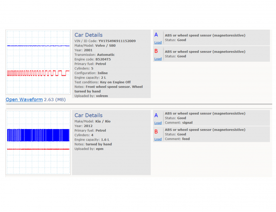
Waveform library
The Waveform Library is a global database of waveforms uploaded by PicoScope users.

Case studies
Real-life case studies show how the professionals use PicoScope to diagnose vehicle faults.

A to Z of PicoScope
Detailed description of various PicoScope software and hardware features.

Videos
Training resources and demonstrations on PicoScope and the Automotive Diagnostics Kit.

Newsletter
Archive of our monthly Automotive Newsletters.

Documentation
Download manuals, brochures, posters, and training materials.

Reviews and awards
Accolades for the preferred diagnostic tool for service centers and vehicle manufacturers.


Multimeter Probes

Back-pinning Probe Set

PicoScope Battery Clip
*At Pico we are always looking to improve our products. The tools used in this guided test may have been superseded and the products above are our latest versions used to diagnose the fault documented in this case study.
The purpose of this test is to evaluate the operation of an Antilock Braking System (ABS) magnetoresistive wheel speed sensor based upon its output voltage and frequency.

View connection guidance notes.
.
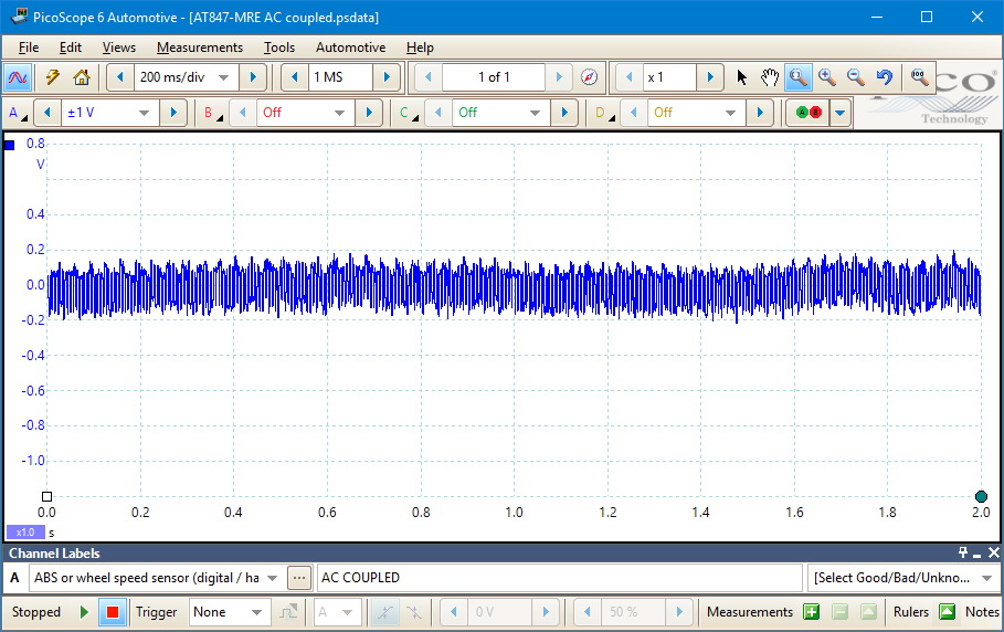
This known good waveform has the following characteristics:
Go to the drop-down menu bar at the lower left corner of the Waveform Library window and select, ABS or wheel speed sensor (magnetoresistive).


Wheel speed sensors provide wheel and road speed feedback to ABS and derivative active vehicle safety systems (i.e. stability and traction control etc.).
These systems are designed to provide corrective action (e.g. wheel braking or engine torque limitation) when the vehicle chassis or wheel speeds have exceeded their normal operational tolerances, for example, during conditions of wheel slip, oversteer or understeer etc. Wheel speed sensors are critical to the operation of these systems and, therefore, the safe handling of a vehicle.
A magnetoresistive wheel speed sensor includes a semiconductor, a Magneto Resistive Element (MRE), that acts as either a conductor or an insulator depending on the orientation of any nearby magnetic field. When in the presence of an alternating magnetic field, as provided by a multipole rotor ring mounted in a wheel bearing seal or hub assembly, the sensor switches its output on and off. This action produces a digital square wave which is received by the ABS control module.
Magnetoresistive sensors require power to operate; hence they are referred to as active sensors. These sensors usually have two terminals with a constant earth reference on one and a combined supply (often at battery voltage) and signal circuit on the other. The combined supply voltage and signal waveform can be measured in two possible PicoScope modes: with the DC offset from the supply voltage present (DC coupled mode) or AC coupled to show only the changing output signal (as in the example above).
It is not easily possible to distinguish two wire passive (inductive) and active (Hall or magnetoresistive) wheel speed sensors by their external appearance. Diagnostically, this is inconvenient as active wheel speed sensors must never be subjected to resistance tests: this can damage these units, with the only remedy being the acquisition of a new replacement.
Therefore, you must always either consult manufacturer’s data to identify the fitted type prior to diagnostic testing or carry out a speculative PicoScope check to identify the sensor from its output voltage characteristics.
You can check for a positive supply voltage at one of the sensor connector terminals to determine if you have an active sensor type. However, if the supply voltage is missing due to a fault and you then assume the sensor must be passive and perform a resistance check, you can damage a perfectly good active sensor. This will give you two faults.
An ABS control module expects similar (within a given tolerance) oscillation frequencies from all the vehicle’s wheel speed sensors and uses any differences to calculate the timing and scale of its interventions.
If one, or more, wheel speed signals continuously fall outside of normal parameters the control module may turn the ABS function off (along with associated traction and stability systems). A driver warning light will be illuminated but, as with any electrical fault on ABS, normal hydraulic braking is maintained.
Wheel speed sensors and their pulse rings are exposed to the atmosphere and have to operate under conditions of constant vibration and movement. As such, common faults are:
Wheel speed sensor circuits and connectors are also prone to the atmosphere and possible electrical failures, such as open or short circuits or high circuit resistances.
Active wheel speed sensors are susceptible to damage from incorrect testing methods; in particular, the application of resistance testing.
Symptoms of ABS sensor related faults
Selection of component related diagnostic trouble codes.
C0000 - Vehicle Speed Information Circuit Malfunction
C0035 - Left Front Wheel Speed Circuit Malfunction
C0040 - Right Front Wheel Speed Circuit Malfunction
C0041 - Right Front Wheel Speed Sensor Circuit Range/Performance (EBCM)
C0045 - Left Rear Wheel Speed Circuit Malfunction
C0046 - Left Rear Wheel Speed Sensor Circuit Range/Performance (EBCM)
C0050 - Right Rear Wheel Speed Circuit Malfunction
C0051 - LF Wheel Speed Sensor Circuit Range/Performance (EBCM)
C0060 - Left Front ABS Solenoid #1 Circuit Malfunction
C0065 - Left Front ABS Solenoid #2 Circuit Malfunction
C0070 - Right Front ABS Solenoid #1 Circuit Malfunction
C0075 - Right Front ABS Solenoid #2 Circuit Malfunction
C0080 - Left Rear ABS Solenoid #1 Circuit Malfunction
C0085 - Left Rear ABS Solenoid #2 Circuit Malfunction
C0090 - Right Rear ABS Solenoid #1 Circuit Malfunction
C0095 - Right Rear ABS Solenoid #2 Circuit Malfunction
C0110 - Pump Motor Circuit Malfunction
C0121 - Valve Relay Circuit Malfunction
C0128 - Low Brake Fluid Circuit Low
C0141 - Left TCS Solenoid #1 Circuit Malfunction
C0146 - Left TCS Solenoid #2 Circuit Malfunction
C0151 - Right TCS Solenoid #1 Circuit Malfunction
C0156 - Right TCS Solenoid #2 Circuit Malfunction
C0161 - ABS/TCS Brake Switch Circuit Malfunction
C0221 - Right Front Wheel Speed Sensor Circuit Open
C0222 - Right Front Wheel Speed Signal Missing
C0223 - Right Front Wheel Speed Signal Erratic
C0225 - Left Front Wheel Speed Sensor Circuit Open
C0226 - Left Front Wheel Speed Signal Missing
C0227 - Left Front Wheel Speed Signal Erratic
C0229 - Drop Out of Front Wheel Speed Signals
C0235 - Rear Wheel Speed Signal Circuit Open
C0236 - Rear Wheel Speed Signal Circuit Missing
C0237 - Rear Wheel Speed Signal Erratic
C0238 - Wheel Speed Mismatch
C0241 - EBCM Control Valve Circuit
C0245 - Wheel Speed Sensor Frequency Error
C0254 - EBCM Control Valve Circuit
C0265 - EBCM Relay Circuit
C0266 - EBCM Relay Circuit
C0267 - Pump Motor Circuit Open/Shorted
C0268 - Pump Motor Circuit Open/Shorted
C0269 - Excessive Dump/Isolation Time
C0271 - EBCM Malfunction
C0272 - EBCM Malfunction
C0273 - EBCM Malfunction
C0274 - Excessive Dump/Isolation Time
C0279 - Powertrain Configuration Not Valid
C0281 - Brake Switch Circuit
C0283 - Traction Switch Shorted to Ground
C0284 - EBCM Malfunction
C0286 - ABS Indicator Lamp Circuit Shorted to B+
GT847
Disclaimer
This help topic is subject to changes without notification. The information within is carefully checked and considered to be correct. This information is an example of our investigations and findings and is not a definitive procedure.
Pico Technology accepts no responsibility for inaccuracies. Each vehicle may be different and require unique test
settings.
We know that our PicoScope users are clever and creative and we’d love to receive your ideas for improvement on this test. Click the Add comment button to leave your feedback.


