PicoScope 7 Automotive
Available for Windows, Mac, and Linux, the next evolution of our diagnostic scope software is now available.
Automotive guided tests
Library of examples on how to perform tests when using PicoScope.

Training
Our collection of training videos, articles, guides and information on training courses.

Waveform library
The Waveform Library is a global database of waveforms uploaded by PicoScope users.

Case studies
Real-life case studies show how the professionals use PicoScope to diagnose vehicle faults.

A to Z of PicoScope
Detailed description of various PicoScope software and hardware features.

Videos
Training resources and demonstrations on PicoScope and the Automotive Diagnostics Kit.

Newsletter
Archive of our monthly Automotive Newsletters.

Documentation
Download manuals, brochures, posters, and training materials.

Reviews and awards
Accolades for the preferred diagnostic tool for service centers and vehicle manufacturers.


Back-pinning Probe Set

Flexible Back-pinning Probe

Small Crocodile/Gator Clips

PicoScope Sprung Hook Probe

PicoScope Battery Clip

Large Dolphin/Gator Clips

Premium Test Lead: BNC to 4 mm, 3 m

Premium Test Leads: Set of four leads 3 m (TA125 - TA128)
*At Pico we are always looking to improve our products. The tools used in this guided test may have been superseded and the products above are our latest versions used to diagnose the fault documented in this case study.
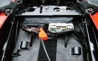
Plug the x20 attenuator into Channel A of the scope and connect a BNC test lead to the attenuator. Place a small black clip on the lead end with a black moulding (negative) and a Back-pinning Probe onto the end with a red moulding (positive). Place the small black clip onto the motorcycle frame or battery negative, as illustrated in Figure 1. Check the manufacturer's pin data for the combined ignition and injection Electronic Control Module (ECM) coil pack primary connection terminals. Back-probe the correct multiplug pin with the Back-pinning Probe as in Figure 2. Ensure that a good connection is made through to the wire or terminal and the probe has pierced through the wire and plug insulation.
With the example waveform displayed on the screen you can now hit the space bar to start looking at live readings.
 waveform")
The ignition primary waveform is probably one of the most important waveforms that needs to be monitored as its condition is vital to the ignition coil output.
There are basically three areas that need to be observed. These are:
The ignition primary waveform consists of the readings seen on the negative side of the ignition coil. The earth path of the coil can produce over 350 volts.
Within the primary picture there are several sections that need closer examination. In the waveform shown, the horizontal voltage line at the centre of the oscilloscope is at a fairly constant voltage of about 40 volts, which then drops sharply into what is referred to as the coil oscillation.
The length of the above-mentioned horizontal voltage line is the 'spark duration' or 'burn time', which in this case is about 1.5 ms. The coil oscillation period should display a minimum number of 4 to 5 peaks (both upper and lower). A loss of peaks would indicate that the coil needs changing for another of comparable values.
There is no current in the coil's primary circuit until the dwell period, when the coil is earthed and the voltage drops to zero.
The dwell period is controlled by the ignition amplifier and the length of the dwell is determined by the time it takes to build up to about 6-8 amps. When this predetermined current has been reached, the amplifier stops increasing the primary current and it is maintained until the earth is removed from the coil, at the precise moment of ignition.
The vertical line at the centre of the trace is in excess of 350 volts, and is called the 'induced voltage'. This is produced by a process called magnetic induction. At the point of ignition, the coil's earth circuit is removed and the magnetic field or flux collapses across the coil's windings. This in turn induces an average voltage between 250 to 350 volts.
The coil's High Tension (HT) output is proportional to the induced voltage. The height of the induced voltage is sometimes referred to as the primary peak volts.
A low induced voltage can be caused by: a faulty ignition coil, poor earthing of the amplifier/ECM (Engine Control Module), or reduced current in the circuit.
Shorter than anticipated spark duration (or burn time) can be caused by incorrect coil fitment, faulty coil, or too high a resistance within the secondary HT circuit.
A reduction in coil oscillations is often the result of a failing igniter/ECM.
Our test vehicle was a Honda motorbike. Below is the ECM multiplug pin data. Pin data will be manufacturer and model specific and this data is shown for illustration purposes only.

 pin data")
AT115-2
Disclaimer
This help topic is subject to changes without notification. The information within is carefully checked and considered to be correct. This information is an example of our investigations and findings and is not a definitive procedure.
Pico Technology accepts no responsibility for inaccuracies. Each vehicle may be different and require unique test
settings.
We know that our PicoScope users are clever and creative and we’d love to receive your ideas for improvement on this test. Click the Add comment button to leave your feedback.


