PicoScope 7 Automotive
Available for Windows, Mac, and Linux, the next evolution of our diagnostic scope software is now available.
Automotive guided tests
Library of examples on how to perform tests when using PicoScope.

Training
Our collection of training videos, articles, guides and information on training courses.

Waveform library
The Waveform Library is a global database of waveforms uploaded by PicoScope users.

Case studies
Real-life case studies show how the professionals use PicoScope to diagnose vehicle faults.

A to Z of PicoScope
Detailed description of various PicoScope software and hardware features.

Videos
Training resources and demonstrations on PicoScope and the Automotive Diagnostics Kit.

Newsletter
Archive of our monthly Automotive Newsletters.

Documentation
Download manuals, brochures, posters, and training materials.

Reviews and awards
Accolades for the preferred diagnostic tool for service centers and vehicle manufacturers.


Back-pinning Probe Set

Flexible Back-pinning Probe

Large Dolphin/Gator Clips
*At Pico we are always looking to improve our products. The tools used in this guided test may have been superseded and the products above are our latest versions used to diagnose the fault documented in this case study.
The purpose of this test is to investigate the presence of LIN-BUS signals and circuit integrity in relation to systems connected.

View connection guidance notes.
Note:
LIN-BUS circuit access can be gained at individually controlled components.
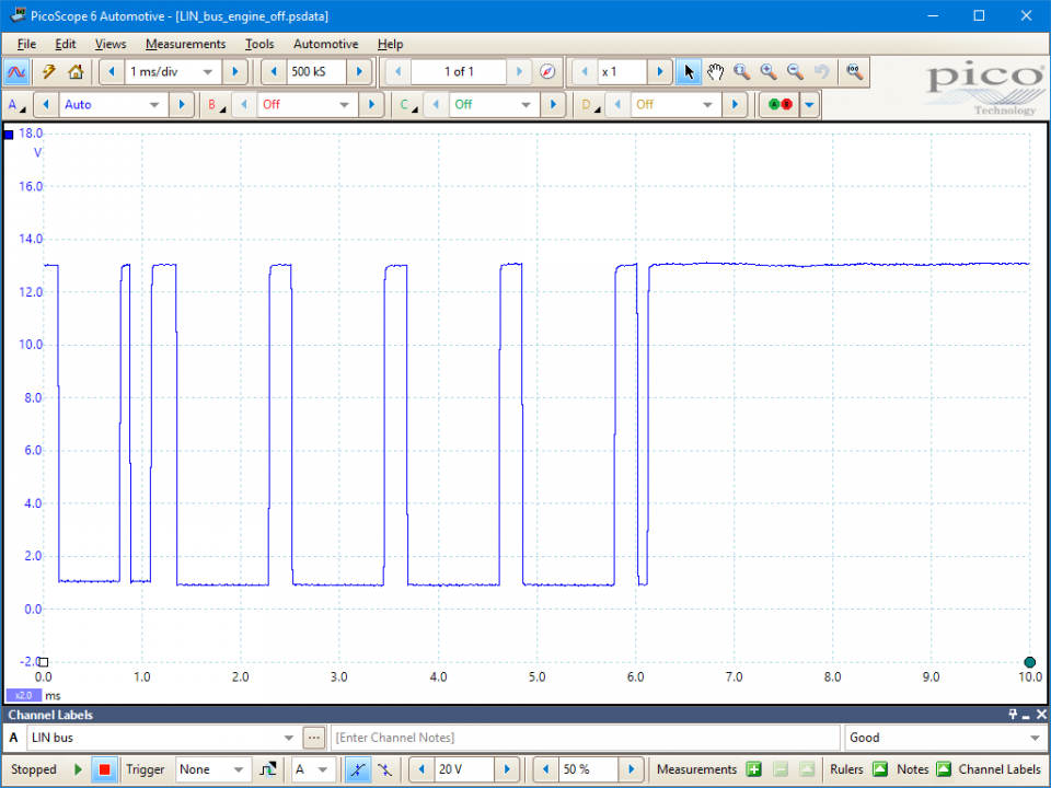
As you can see from the example waveform, the LIN bus waveform is a square wave, representing the binary states in a serial data stream. The waveform observed should be free of obvious distortion and noise spikes, and the upper and lower levels should be approximately as in the example (for a 12 V system).
The lower level voltage (logic zero) should be less than 20% of battery voltage (typically 1 V) and the upper level voltage (logic one) should be more than 80% of battery voltage. Note that the voltage levels may change slightly when the engine is started.
We cannot decode the data stream using a scope, so the purpose of this test is to verify that the signal is both present and correct, and is not interrupted by moving the wiring harness or gently tugging the connectors. Faults may be specific to a particular function, such as a non-operating window, or general, where all the functions on the bus are not working. Before condemning a device, use the scope to check that it has power, ground, and a present and correct LIN signal.
Go to the drop-down menu bar at the lower left corner of the Waveform Library window and select, Lin bus

Local Interconnect Network (LIN) bus communication is becoming more common on modern CAN Bus-equipped vehicles. It is essentially a low-speed, single-wire serial data bus (a sub-bus of the faster, more complex CAN Bus) used to control low-speed non-safety-critical housekeeping functions on the vehicle, especially windows, mirrors, locks, HVAC units, and electric seats.
The LIN bus is proving popular because of its low cost and also because it reduces the bus load of the supervising CAN network.
AT124-2
Disclaimer
This help topic is subject to changes without notification. The information within is carefully checked and considered to be correct. This information is an example of our investigations and findings and is not a definitive procedure.
Pico Technology accepts no responsibility for inaccuracies. Each vehicle may be different and require unique test
settings.
We know that our PicoScope users are clever and creative and we’d love to receive your ideas for improvement on this test. Click the Add comment button to leave your feedback.


