PicoScope 7 Automotive
Available for Windows, Mac, and Linux, the next evolution of our diagnostic scope software is now available.
Automotive guided tests
Library of examples on how to perform tests when using PicoScope.

Training
Our collection of training videos, articles, guides and information on training courses.

Waveform library
The Waveform Library is a global database of waveforms uploaded by PicoScope users.

Case studies
Real-life case studies show how the professionals use PicoScope to diagnose vehicle faults.

A to Z of PicoScope
Detailed description of various PicoScope software and hardware features.

Videos
Training resources and demonstrations on PicoScope and the Automotive Diagnostics Kit.

Newsletter
Archive of our monthly Automotive Newsletters.

Documentation
Download manuals, brochures, posters, and training materials.

Reviews and awards
Accolades for the preferred diagnostic tool for service centers and vehicle manufacturers.


Multimeter Probes

Back-pinning Probe Set

Flexible Back-pinning Probe

Large Dolphin/Gator Clips

Premium Test Lead: BNC to 4 mm, 3 m
*At Pico we are always looking to improve our products. The tools used in this guided test may have been superseded and the products above are our latest versions used to diagnose the fault documented in this case study.
The purpose of this test is to evaluate the operation of a piezoelectric knock sensor when subjected to a simulated engine knock.
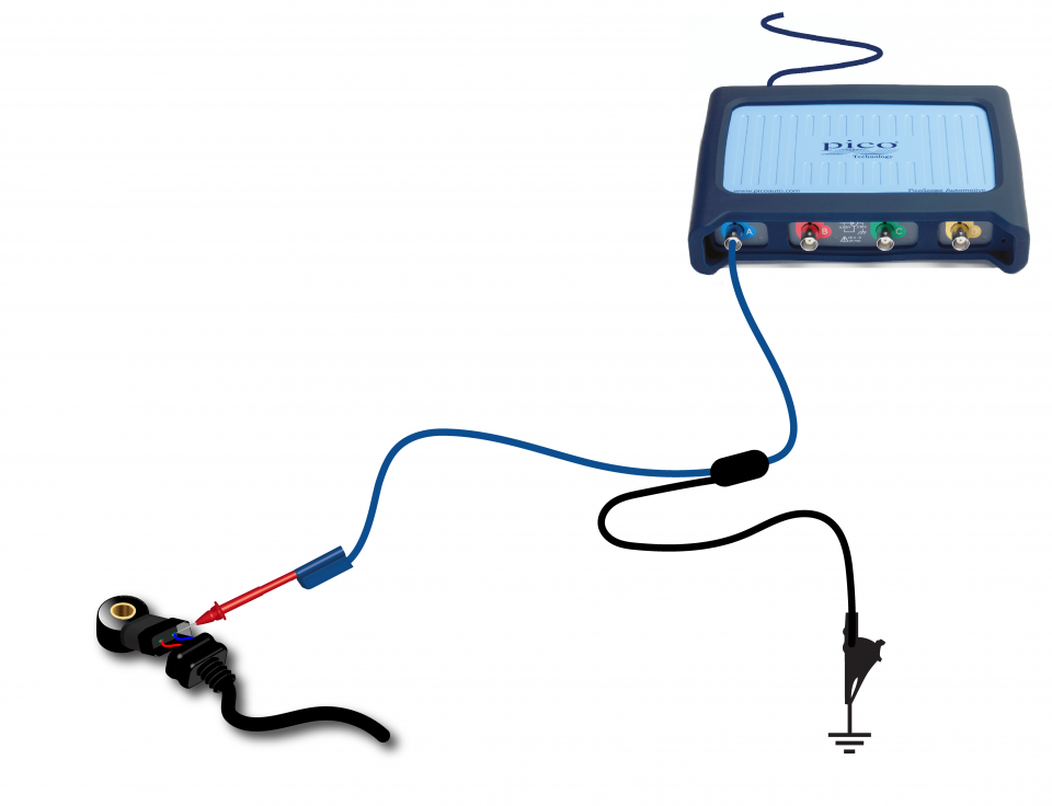
View connection guidance notes.
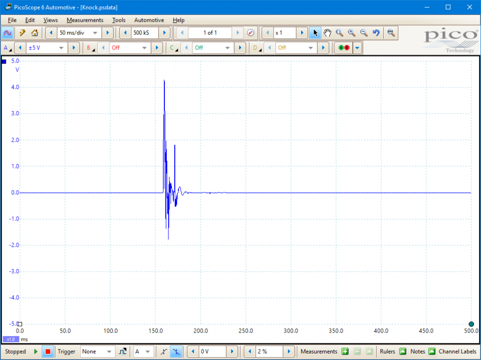
This known good waveform has the following characteristics:
Go to the drop down menu bar at the lower left corner of the Waveform Library window and select Knock sensor.


Knocking (also known as pinking, pinging or detonation) occurs in a spark-ignition engine when pockets of air-fuel mixture combust (explode) outside the area of the normal spark-initiated, flame-front driven, combustion process. The uncontrolled explosions cause structure borne vibrations (causing the characteristic pinking or pinging sound) which are detected by knock sensors mounted on the exterior wall of the engine block.
Knock is a problem, particularly in lean burning or high compression engines, as it can create excessive combustion chamber pressures. If it occurs too frequently or violently it can be highly destructive. The knock limit, the point at which knock becomes excessive, depends upon fuel quality and engine, operating and environmental conditions.
Internal Combustion Engines (ICEs) are most efficient when they create the highest possible peak combustion pressures at the point of most mechanical advantage (just after the crank passes the position of TDC). However, peak combustion pressures need to be regulated to keep knock below the knock limit. The Engine Control Module (ECM) achieves this balancing act by adjusting the point of ignition. By retarding the ignition, so that peak combustion pressure arrives when the piston has travelled further down its power stroke, the ECM can reduce the peak combustion pressure and the likelihood of knock.
As continuously retarded ignition timing will cause less efficient engine operation and reduced power, most ECMs seek to step the ignition back towards a more advanced timing, up until the knock limit is reached (at which point the ECM will again retard the ignition).
Automotive knock sensors fall into two type categories:
Both are piezo crystal devices that convert vibration, via pressure on the piezo crystal, into a voltage.
Some sensors, dependent on application, may be found with three terminals. The third terminal provides a shielding cable for circuits one and two.
Resonant sensors, the earlier development of a knock sensor, are mechanically tuned to a narrow frequency. They can have a slightly higher voltage spike when tested. As the name suggests they continually resonate with their tuned peaks but this makes them susceptible to other noise sources containing the same excitation frequency.
Flat response sensors are able to detect a wider range of vibration from the engine. ECMs can continuously monitor their output to exercise much closer control of ignition. This type of sensor necessitates the use of a built-in open circuit detection resistor.
Associated symptoms
Knock occurs if any of the following are present:
Consistent engine knock, and associated sensor faults, may cause the following symptoms:
Other mechanical faults can produce vibrations that are interpreted by the ECM as knock (for example, dual mass flywheels having excessive play or if there is insufficient oil within the engine). Therefore, they can cause similar symptoms to those listed above.
System faults
Knock sensors can be susceptible to mechanical faults, such as:
Knock sensors and their circuits are also susceptible to typical electrical circuit faults, such as open or short circuits and high resistances.
Selection of Diagnostic Trouble Codes (DTCs):
P0324
P0325
P0326
P0327
P0328
P0329
P0330
P0331
P0332
P0333
P0334
View more
GT021
Disclaimer
This help topic is subject to changes without notification. The information within is carefully checked and considered to be correct. This information is an example of our investigations and findings and is not a definitive procedure.
Pico Technology accepts no responsibility for inaccuracies. Each vehicle may be different and require unique test
settings.
We know that our PicoScope users are clever and creative and we’d love to receive your ideas for improvement on this test. Click the Add comment button to leave your feedback.


