PicoScope 7 Automotive
Available for Windows, Mac, and Linux, the next evolution of our diagnostic scope software is now available.
Automotive guided tests
Library of examples on how to perform tests when using PicoScope.

Training
Our collection of training videos, articles, guides and information on training courses.

Waveform library
The Waveform Library is a global database of waveforms uploaded by PicoScope users.

Case studies
Real-life case studies show how the professionals use PicoScope to diagnose vehicle faults.

A to Z of PicoScope
Detailed description of various PicoScope software and hardware features.

Videos
Training resources and demonstrations on PicoScope and the Automotive Diagnostics Kit.

Newsletter
Archive of our monthly Automotive Newsletters.

Documentation
Download manuals, brochures, posters, and training materials.

Reviews and awards
Accolades for the preferred diagnostic tool for service centers and vehicle manufacturers.


CAN Test Box

Back-pinning Probe Set

Flexible Back-pinning Probe

PicoScope Battery Clip

Large Dolphin/Gator Clips

Premium Test Lead: BNC to 4 mm, 3 m

Premium Test Leads: Set of four leads 3 m (TA125 - TA128)
*At Pico we are always looking to improve our products. The tools used in this guided test may have been superseded and the products above are our latest versions used to diagnose the fault documented in this case study.
The purpose of this test is to verify that data is being continuously exchanged along the K-Line, and it is possible to check that the peak-to-peak voltage levels are correct and that a signal is present during the communication between the scan tool and the ECM.
If you don't have the CAN Test Box, see "Testing Without the CAN Test Box" below.
Battery V+: Pin 16
Chassis GND: Pin 4
Signal GND: Pin 5
See Figures 1 and 2.
The K-Line waveform will now appear on the screen as shown below.
Important: Once the ECM is communicating with the scan tool, pin 7 LED will begin to flash on the CAN Test Box. If the scan tool shows no communication with the ECM and the pin 7 LED is not flashing, then the scan tool is not sending the command to the ECM to communicate.
If, however, the scan tool shows that it has no communication with the ECM and the pin 7 LED is flashing, then the scan tool is sending the command but the ECM is not completing the communication. Causes of this could be poor connections between the DLC and ECM, incorrect scan tool communication command in software, or a fault within the ECM.
The K-Line waveform will now appear on the screen as shown below.
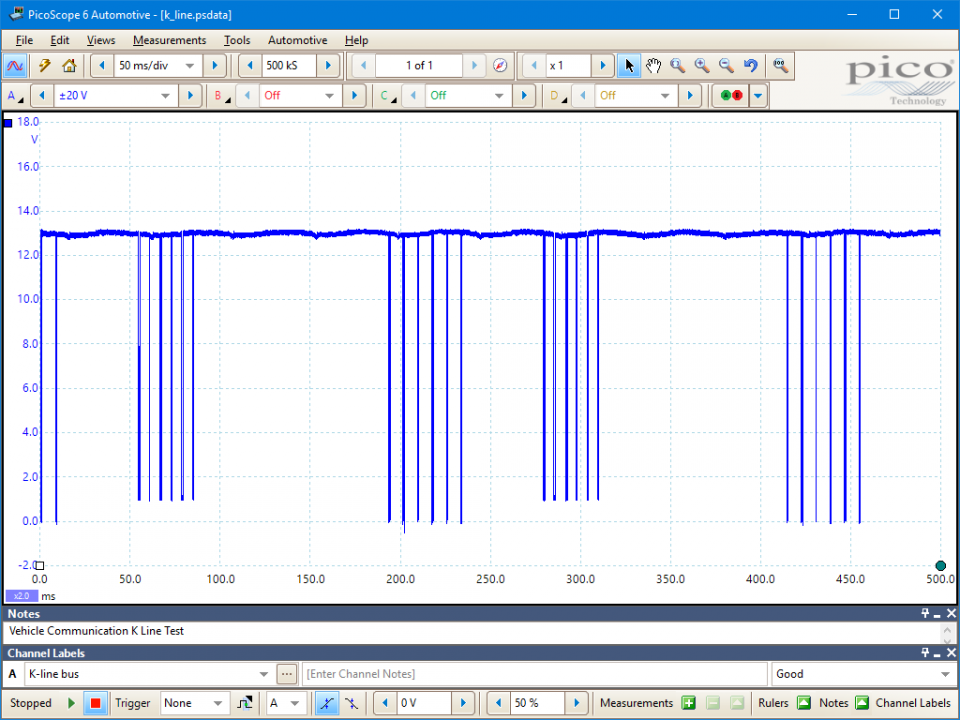
In this display, we can verify that data is being continuously exchanged along the K-Line, and it is possible to check that the peak-to-peak voltage levels are correct and that a signal is present whilst communication is taking place between the scan tool and the ECM. Refer to the vehicle manufacturer's manual for precise waveform parameters.
The K-Line is a very low-speed single-wire serial communication system used on many motor vehicles and commercial vehicles. It is commonly used for the diagnostic connections between the Electronic Control Modules (ECMs) on the vehicle and the diagnostic equipment (scan tools and data loggers). The K-Line is a network based upon the ISO9141 specifications, also known as the 9141 California Air Resources Board (CARB) Standard.
The K-Line is very different to a CAN Bus network and from most communication networks in general. A CAN Bus network, for example, does not have either a central or a primary ECM: all the ECMs are equal as they are all able to transmit messages along the network as well as receive messages.
On the K-Line network or any network compliant with ISO 9141, the direction of message flow is extremely important. The control of the network is dominated by the master ECM, and the message direction and timing depend on which ECM is talking (sending a message) and which ECMs are listening (waiting for a message). Two ECMs therefore cannot send a message at the same time, but have to wait in turn until allowed by the Master ECM. See Figure 3.
The diagram shows that there is only one wire for all communication on the network. The messages therefore need to be sent in binary format and transmitted as a pulsed voltage signal. The voltages on the K-Line are pulsed between two values in binary code (a series of ones and zeroes). The binary code is represented by the voltages shown in Figure 4 below:-
Note: Logic 0 is represented by battery voltage, so may be above 12 V.
Note 1: A K-Line message is different to a CAN message, as CAN always sends an entire message at once while K-Line may send messages split into several parts.
Note 2: A CAN Bus network operates constantly as a communication network and a diagnostic network between the ECMs whilst the vehicle is in operation. The K-Line network is only intended to support diagnostic equipment. However, when a diagnostic machine is not present, the K-Line wiring may be used by other ECMs for communication at different baud rates and with different timing patterns.
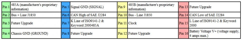
The 16 pins of the DLC are available on the CAN Test Box and are numbered as follows:
AT166-3
Disclaimer
This help topic is subject to changes without notification. The information within is carefully checked and considered to be correct. This information is an example of our investigations and findings and is not a definitive procedure.
Pico Technology accepts no responsibility for inaccuracies. Each vehicle may be different and require unique test
settings.
We know that our PicoScope users are clever and creative and we’d love to receive your ideas for improvement on this test. Click the Add comment button to leave your feedback.


