PicoScope 7 Automotive
Available for Windows, Mac, and Linux, the next evolution of our diagnostic scope software is now available.
Automotive guided tests
Library of examples on how to perform tests when using PicoScope.

Training
Our collection of training videos, articles, guides and information on training courses.

Waveform library
The Waveform Library is a global database of waveforms uploaded by PicoScope users.

Case studies
Real-life case studies show how the professionals use PicoScope to diagnose vehicle faults.

A to Z of PicoScope
Detailed description of various PicoScope software and hardware features.

Videos
Training resources and demonstrations on PicoScope and the Automotive Diagnostics Kit.

Newsletter
Archive of our monthly Automotive Newsletters.

Documentation
Download manuals, brochures, posters, and training materials.

Reviews and awards
Accolades for the preferred diagnostic tool for service centers and vehicle manufacturers.

(without variable valve lift inc. WOT snap test)
The purpose of this test is to rapidly confirm the operation of the turbocharger, from idle speed through to a wide open throttle (WOT) "snap" test, then returning to idle speed.
This procedure is not a definitive test for your turbocharger. It does, however, confirm the presence of a positive pressure (above atmospheric) during the WOT snap test, confirming the rotation of the turbine and compressor shaft.
Turbocharger boost pressure is directly related to:
All numerical readings quoted in this help topic are typical and are not applicable to all engine styles.
All the values below are obtained with the WPS500X are referenced to gauge pressure.
Intake pressure before the throttle (air inlet side) is described here as atmospheric pressure = 0 mbar.
Intake pressure after the throttle (engine side, negative pressure) is described here as vacuum = below 0 mbar.
Intake pressure after the throttle during the WOT snap test is described here as a positive pressure = above 0 mbar, Boost pressure
Make sure that the WPS500X is fully charged before you start this test.
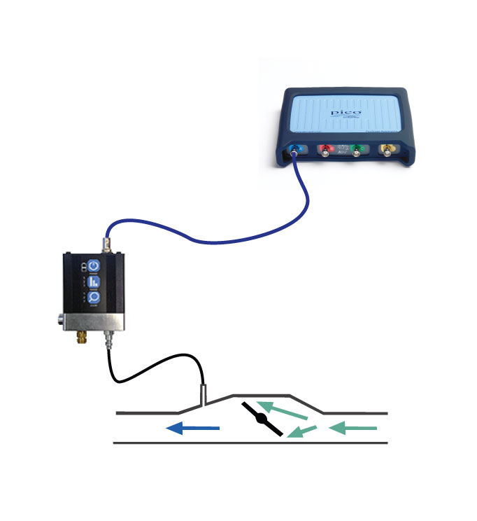
How to perform the test
Accessories
PicoScope settings
We advise that you recharge your WPS500X after each use to ensure it is ready for future measurements.
Example waveform

Channel A shows the intake manifold vacuum/pressure during the various stages of the test (steps 8 and 9).
The green line (at marker 3) denotes atmospheric pressure 0 mbar
The black ruler (at marker 1) denotes idle intake vacuum, approximately -560 mbar
The orange arrow (at marker 4) denotes the initial delay from the start point of WOT to the commencement of positive pressure (at marker 5) building inside the intake manifold. Referred to as Turbo lag. The example waveform vehicle measures 600 ms approx.
The orange arrow (at marker 6) denotes the time taken for the intake manifold pressure to build to its peak of +560 mbar (at marker 7), from the initial increase by marker 5.
By adding the time indicated by the orange arrows at markers 4 and 6, you can calculate the total time taken to achieve maximum manifold pressure (boost pressure) from the initial WOT at marker 2. (1.1 seconds approx. on our test vehicle.)
The purple arrow (at marker 7) denotes the maximum positive manifold pressure (above atmospheric) produced by the turbocharger, Boost pressure.
The blue line (at marker 9) denotes the maximum manifold vacuum, approximately -820 mbar.
Key to Example waveform:
1. Stable idle speed–note the stable manifold vacuum
2. WOT applied–rapid decrease in manifold vacuum to atmospheric pressure (0 mbar).
3. Atmospheric pressure–the throttle is held wide open.
4. Initial Turbo lag before intake manifold pressure begins to increase.
5. Commencement of intake manifold pressure above atmospheric (boost pressure).
6. Elapsed time for intake manifold pressure to rise to maximum boost pressure from commencement at marker 5.
7. Maximum boost pressure.
8. Rapid decrease in manifold boost pressure, falling below atmospheric pressure into a vacuum
9. Increased intake pocket during over-run–note the increase in manifold vacuum below the stable idle at marker 1.
Diagnosis
Refer to the vehicle’s technical data for specific test conditions and results.
Typical values (when the engine is at correct operating temperature).
1. Stable idle speed
When idle speed stabilization has been executed by the engine management and all loads applied to the engine have settled, the idle speed manifold vacuum should remain reasonably stable on this time base.
For more accurate analysis at idle speed refer to Pressure Sensors > WPS500X Pressure Transducer > Intake Manifold Pressure-Idle Speed pre-set on the Automotive menu.
2. WOT applied
Applying WOT, with the engine at the correct operating temperature, should result in an instant fall in manifold vacuum, reverting to the atmospheric pressure (0 mbar) indicated by the green line at marker 3.
3. WOT held
There will be no restriction inside the intake manifold while the throttle is held open. As a result, the intake manifold will remain equal to atmospheric pressure until the turbocharger speed increases sufficiently to generate a positive pressure (boost pressure at marker 5).
4. Turbo Lag
From the instant the throttle is help wide open, an inevitable delay will be experienced before the commencement of positive pressure building inside the intake manifold. This is referred to as Turbo lag. The example waveform vehicle measures approximately 600 ms. (indicated by arrow with marker 4).
5. Commencement of positive pressure (boost)
As the engine speed continues to increase, the speed of the turbocharger’s turbine and compressor shaft will increase to a point where a positive pressure is generated inside the intake manifold. This initial increase in manifold pressure (above atmospheric) is indicated by marker 5.
6. Elapsed time from commencement of boost to maximum boost pressure
The time for the intake manifold pressure to increase from the commencement of boost pressure at marker 5, to the maximum boost pressure at marker 7, is indicted by arrow with marker 6. In the example waveform the time was approximately 470 ms
7. Maximum boost pressure
The continued increase in the turbocharger’s turbine and compressor shaft speed during the WOT stage, results in a rapid increase in manifold pressure to the maximum boost pressure recorded at marker 7 (highlighted with the purple arrow). Please be aware that the value recorded here must only be used as an indication of turbocharger activity, (confirming rotation of the turbine and compressor shaft) and not a definitive guide to the efficiency of the turbocharger. Various manufactures will limit the turbocharger maximum boost values when the vehicle is stationary. This highlights the need to carry out a similar test under road test conditions. Make sure that the maximum boost pressure does not exceed the manufacturers stated value as this could indicate a sticking turbocharger waste gate/vane control mechanism or failure within the maximum boost control circuit.
8. Rapid decrease in manifold pressure
When you release the throttle pedal, both the engine speed and the turbocharger’s turbine and compressor shaft speed will decrease, resulting in a fall in boost pressure to below atmospheric pressure, and returning to a vacuum. Be aware that the turbocharger speed and engine speed will fall at differing rates resulting in a progressive return into a vacuum as opposed to a rapid return with non-turbocharged engines.
9. Increased intake pocket
Given the engine speed is high but falling after the WOT test (throttle now closed) the intake manifold vacuum continues to rise above the stable idle speed level (at marker 1) to form the intake pocket. Here you can further confirm the mechanical efficiency of the engine and the integrity of the intake system. A small intake pocket could indicate a mechanical defect or intake leak. For more accurate analysis of the intake pocket refer to Pressure Sensors > WPS500X Pressure Transducer > Intake Manifold Pressure-WOT Snap Test pre-set on the Automotive menu.
More information
Throttle closed

Throttle open


The turbocharger has been developed to provide a greater volumetric efficiency for a given engine size, or in other words, to improve just how efficiently air can flow in and out of the combustion chamber.
Increasing the volume of air allows for an increase in the volume of fuel to be added, resulting in an increase in power output.
While we often associate the turbocharger with large high performance engines, modern emissions regulations have seen an increase in the use of turbochargers linked to smaller efficient engines with reduced cylinder counts and capacities.
The use of the turbocharger therefore allows for a reduction in engine weight, size and emissions without sacrificing performance, which can only result in an increase in turbocharger applications.
The turbocharger is mounted into the exhaust manifold in such a way as to expose the turbine to the exhaust gasses leaving the combustion chamber on route through the exhaust system. The turbine is linked to a compressor via the turbine compressor shaft, where any rotation of the turbine results in an identical rotation of the compressor.
The compressor is mounted in the air intake of the engine, increasing the intake air pressure and volume as the compressor rotational speed increases.
There is, however, an inherent characteristic to be aware of with turbocharger operation. Turbo lag is the name given to describe the delay in response of the turbine and compressor shaft speed in relation to the volume of exhaust gases passing over the turbine. In order to provide the greatest boost pressure in the minimum time requires the engine to be subjected to wide open throttle (WOT) conditions producing high volumes of exhaust gasses directed towards the turbine assembly.
While the boost pressure will provide an increase in the volumetric efficiency, accompanied with an increase in power output, over-boost conditions put the integrity of the engine components at risk, and can result in severe engine damage.
Over-boost control is implemented by reducing the speed of the turbocharger compressor and turbine shaft speed. Given turbine speed is dependent on the flow and volume of exhaust gas passing over the vanes of the turbine. By redirecting the exhaust gasses away from the turbine, we can reduce the turbine/compressor speed and so reduce the turbo boost to a safe operating level.
By-passing the turbine is achieved by the use of a wastegate controlled directly by boost pressure applied to an actuator linked to the wastegate, or via the ECU applying pressure/electronic control signal to the wastegate actuator dependent of information received from the MAP sensor.
Warning
Do not switch off the engine immediately after revving as the turbocharger speed will remain high while the oil pressure supplied to the turbocharger will fall rapidly. This will lead to the undesirable condition of the turbocharger rotating at speeds in excess of 100,000 rpm with no oil supply/lubrication. After free revving a turbocharged engine, let the engine idle for 30 seconds before you switch it off.
Disclaimer
This help topic is subject to changes without notification. The information within is carefully checked and considered to be correct. This information is an example of our investigations and findings and is not a definitive procedure.
Pico Technology accepts no responsibility for inaccuracies. Each vehicle may be different and require unique test
settings.
We know that our PicoScope users are clever and creative and we’d love to receive your ideas for improvement on this test. Click the Add comment button to leave your feedback.


