PicoScope 7 Automotive
Available for Windows, Mac, and Linux, the next evolution of our diagnostic scope software is now available.
Automotive guided tests
Library of examples on how to perform tests when using PicoScope.

Training
Our collection of training videos, articles, guides and information on training courses.

Waveform library
The Waveform Library is a global database of waveforms uploaded by PicoScope users.

Case studies
Real-life case studies show how the professionals use PicoScope to diagnose vehicle faults.

A to Z of PicoScope
Detailed description of various PicoScope software and hardware features.

Videos
Training resources and demonstrations on PicoScope and the Automotive Diagnostics Kit.

Newsletter
Archive of our monthly Automotive Newsletters.

Documentation
Download manuals, brochures, posters, and training materials.

Reviews and awards
Accolades for the preferred diagnostic tool for service centers and vehicle manufacturers.


FirstLook Engine Diagnostic Sensor

Secondary ignition pickup (capacitive with BNC)
*At Pico we are always looking to improve our products. The tools used in this guided test may have been superseded and the products above are our latest versions used to diagnose the fault documented in this case study.
The purpose of this test is to assess engine condition during cranking by using the FirstLook™ sensor to observe exhaust pulsation.
WARNING
Uninsulated HT pickups are designed to clip around double-insulated HT leads only – they are not designed for direct connection to a hazardous live voltage.
To prevent injury or death, when connecting or disconnecting an HT pickup:

View connection guidance notes.
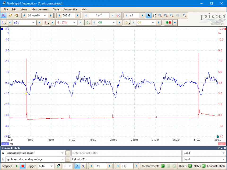
These known good waveforms have the following characteristics:
Go to the drop-down menu bar at the lower left corner of the Waveform Library window and select Exhaust / tailpipe pressure waveform.
The FirstLook™ sensor contains a piezo crystal device which converts pressure pulsations to a voltage signal output. The output can be taken as an indication of the underlying physical actions causing the pressure pulsations.
When checking engine condition by examination of exhaust pulsations, several factors must be taken into account:
For these reasons you should ensure the pulsations have stabilized before examining for engine diagnosis.
With constant engine operating conditions, each cylinder should produce the same pulsation and you should expect uniformity across cylinders.
There are generic pressure pulsation features that may be observed with an internal combustion, piston, engine:
These features may be more prominent within a cranking engine, where the overall gas speed is slower and less smooth than with a running engine.
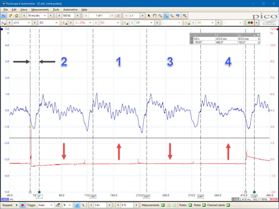
Cylinder identification
Should you suspect an anomaly within the pattern then you will need to identify the offending cylinder. However, both of our captured waveforms introduce a small uncertainty as to the reference points we should use within that process. These uncertainties are:
At low engine speeds (e.g. at idle), the pulse propagation delay can be just under half a pulse width in a 12-cylinder engine but it is proportionally less in engines having fewer cylinders. In all cases, the peak pulse amplitude will not align as expected with the identified engine phases (which are determined relative to the secondary ignition events) but they do appear within the expected phase.
With the above factors in mind, the process for cylinder identification with an exhaust pressure pulsation waveform is:
Causes of waveform anomalies
Exhaust system faults which may cause waveform anomalies are:
Other engine faults also may affect the waveform:
Intake valvetrain issues (e.g. those listed for the exhaust valvetrain above).
GT129-EN
Disclaimer
This help topic is subject to changes without notification. The information within is carefully checked and considered to be correct. This information is an example of our investigations and findings and is not a definitive procedure.
Pico Technology accepts no responsibility for inaccuracies. Each vehicle may be different and require unique test
settings.
We know that our PicoScope users are clever and creative and we’d love to receive your ideas for improvement on this test. Click the Add comment button to leave your feedback.


