PicoScope 7 Automotive
Available for Windows, Mac, and Linux, the next evolution of our diagnostic scope software is now available.
Automotive guided tests
Library of examples on how to perform tests when using PicoScope.

Training
Our collection of training videos, articles, guides and information on training courses.

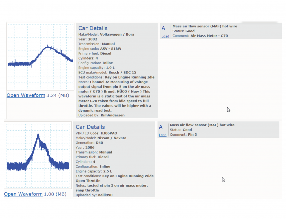
Waveform library
The Waveform Library is a global database of waveforms uploaded by PicoScope users.

Case studies
Real-life case studies show how the professionals use PicoScope to diagnose vehicle faults.

A to Z of PicoScope
Detailed description of various PicoScope software and hardware features.

Videos
Training resources and demonstrations on PicoScope and the Automotive Diagnostics Kit.

Newsletter
Archive of our monthly Automotive Newsletters.

Documentation
Download manuals, brochures, posters, and training materials.

Reviews and awards
Accolades for the preferred diagnostic tool for service centers and vehicle manufacturers.


Back-pinning Probe Set

Flexible Back-pinning Probe

Large Dolphin/Gator Clips

Premium Test Lead: BNC to 4 mm, 3 m

Premium Test Leads: Set of four leads 3 m (TA125 - TA128)
*At Pico we are always looking to improve our products. The tools used in this guided test may have been superseded and the products above are our latest versions used to diagnose the fault documented in this case study.
The purpose of this test is to evaluate the voltage output and response time of the Air Flow Meter (AFM) during engine idle, Wide Open Throttle (WOT) and over-run conditions.
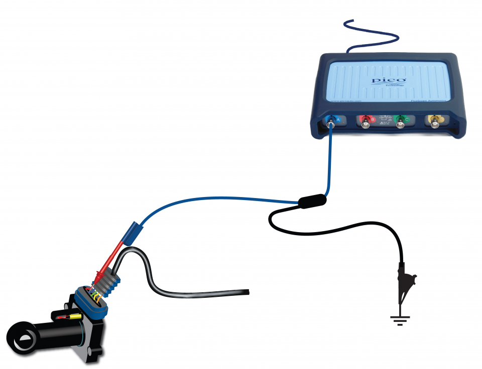
View connection guidance notes.
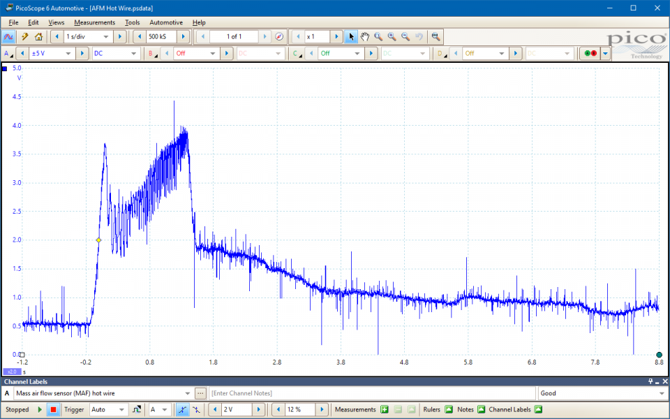
This known good waveform has the following characteristics:
Go to the drop-down menu bar in the lower left corner of the Waveform Library window and select Mass air flow sensor (MAF) hot wire.

Air flow meters measure the quantity of filtered air entering an engine. As such, they are used by the Engine Control Module (ECM) as the primary engine load sensor.
Hot wire air flow meters have a heated wire element located within the intake air flow. The voltage, and hence current, through the hot-wire circuit is varied to keep it at a fixed, hot, temperature. As the air flow increases, its cooling effect increases, and the greater the voltage required to keep the wire temperature constant. Therefore, the hot-wire circuit voltage indicates the air flow to the ECM. The sensor element and air flow meter body form a calibrated unit and are not interchangeable.
Due to their position within the air intake tract, air flow meters can be prone to contamination, e.g. if a vehicle is poorly serviced with ineffectual air filters, or if it has other intake, crankcase breather, or exhaust recirculation faults. In such cases, the meter’s readings can be erroneous, causing the ECM to incorrectly calculate the air-fuel mixture, possibly leading to the following symptoms:
Air flow meter circuits (including the power, ground and signal circuits) are also susceptible to common electrical circuit faults, such as:
Some manufacturers use hot film air flow meters. The testing procedure and operating characteristics are the same as the hot wire type.
Selection of component-related Diagnostic Trouble Codes (DTCs):
P00BC
P00BD
P00BE
P00BF
P0100
P0101
P0102
P0103
P0104
P010A
P010B
P010C
P010D
P010E
View more
GT007-EN
Disclaimer
This help topic is subject to changes without notification. The information within is carefully checked and considered to be correct. This information is an example of our investigations and findings and is not a definitive procedure.
Pico Technology accepts no responsibility for inaccuracies. Each vehicle may be different and require unique test
settings.
We know that our PicoScope users are clever and creative and we’d love to receive your ideas for improvement on this test. Click the Add comment button to leave your feedback.


