PicoScope 7 Automotive
Available for Windows, Mac, and Linux, the next evolution of our diagnostic scope software is now available.
Automotive guided tests
Library of examples on how to perform tests when using PicoScope.

Training
Our collection of training videos, articles, guides and information on training courses.

Waveform library
The Waveform Library is a global database of waveforms uploaded by PicoScope users.

Case studies
Real-life case studies show how the professionals use PicoScope to diagnose vehicle faults.

A to Z of PicoScope
Detailed description of various PicoScope software and hardware features.

Videos
Training resources and demonstrations on PicoScope and the Automotive Diagnostics Kit.

Newsletter
Archive of our monthly Automotive Newsletters.

Documentation
Download manuals, brochures, posters, and training materials.

Reviews and awards
Accolades for the preferred diagnostic tool for service centers and vehicle manufacturers.


200 A / 2000 A (high amps) DC current clamp

600 A DC (high amps) current clamp
*At Pico we are always looking to improve our products. The tools used in this guided test may have been superseded and the products above are our latest versions used to diagnose the fault documented in this case study.
The purpose of this test is to evaluate the condition of the glow plugs and to check their operation time.
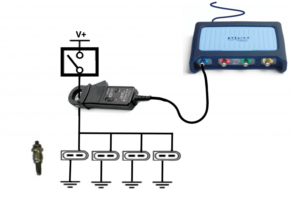
View connection guidance notes.
Note
The glow plugs may not activate if the ambient and engine temperature conditions are not correct.
The orientation of the clamp relative to the wire will determine whether it has a positive or negative output. If a live waveform does not appear on your screen, or appears to be inverted, try reversing the orientation of the clamp.
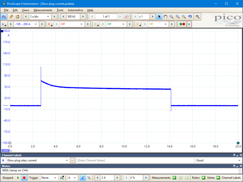
This known good waveform has the following characteristics:
Go to the drop down menu in the lower left corner of the Waveform Library window and select Glow plug current.


Glow plugs support diesel fuel combustion and emissions control processes.
Injected diesel fuel ignites if the cylinder charge temperature reaches 850° C during compression. However, this temperature may not be achieved with cold ambient air conditions and engine components. In these circumstances, the glow plugs are activated to heat the cylinder charge and ensure adequate combustion.
Glow plugs are designed to operate within temperatures from 850° to 1100° C. They are controlled by a relay switched by either the Engine Control Module (ECM) or by a dedicated glow plug control unit/timer. The system switching and on time characteristics will vary with vehicle.
Glow plugs also heat the cylinder charge to support the operation of diesel particulate filter (DPF) systems: a DPF requires very high exhaust temperatures during passive and active (either running or forced) regeneration processes. Any fault in the glow plug system will prevent regeneration and will inevitably lead to the excessive build-up of particulates in the filter and eventual blockage.
One of the main causes of glow plug failure is overheating. Therefore, some systems use Pulse Width Modulation (PWM) of the supply voltage to regulate the circuit current and to control glow plug temperature.
The expected circuit current is calculated by dividing the total power consumption of all glow plugs (individual plug wattages are available in the appropriate technical literature) by the circuit feed voltage (current = power / voltage).
For example, if a 12 V, 4-cylinder diesel engine with 150 W glow plugs, has a total power consumption of 600 W (4 x 150 W), the expected steady-state circuit current will be around 50 A (600 W / 12 V).
It is important to be able to identify control system failures, such as those that might occur in the ECM, glow control module, or other relays, as a cause of glow plug failure.
Glow plug circuits are susceptible to a variety of faults, such as:
Symptoms of failed glow plugs:
Diagnostic trouble codes
Selection of component related Diagnostic Trouble Codes (DTCs):
P037D
P037E
P037F
P0380
P0381
P0382
P0383
P0384
P064C
P066A
P066B
P066C
P066D
P066E
P066F
P0670
P0671
P0672
P0673
P0674
P0675
P0676
P0677
P0678
P0679
P067A
P067B
P067C
P067D
P067E
P067F
P0680
P0681
P0682
P0683
P0684
P068C
P068D
P068E
P068F
P069A
P069B
P069C
P069D
P06B9
P06BA
P06BB
P06BC
P06BD
P06BE
P06BF
P06C0
P06C1
P06C2
P06C3
P06C4
P06C5
P06C6
P06C7
P06C8
P06C9
P06CA
P06CB
P06CC
P06CD
P06CE
P06CF
P06D0
U0106
U0307
U0407
View more
GT006-EN
Disclaimer
This help topic is subject to changes without notification. The information within is carefully checked and considered to be correct. This information is an example of our investigations and findings and is not a definitive procedure.
Pico Technology accepts no responsibility for inaccuracies. Each vehicle may be different and require unique test
settings.
We know that our PicoScope users are clever and creative and we’d love to receive your ideas for improvement on this test. Click the Add comment button to leave your feedback.


