PicoScope 7 Automotive
Available for Windows, Mac, and Linux, the next evolution of our diagnostic scope software is now available.
Automotive guided tests
Library of examples on how to perform tests when using PicoScope.

Training
Our collection of training videos, articles, guides and information on training courses.

Waveform library
The Waveform Library is a global database of waveforms uploaded by PicoScope users.

Case studies
Real-life case studies show how the professionals use PicoScope to diagnose vehicle faults.

A to Z of PicoScope
Detailed description of various PicoScope software and hardware features.

Videos
Training resources and demonstrations on PicoScope and the Automotive Diagnostics Kit.

Newsletter
Archive of our monthly Automotive Newsletters.

Documentation
Download manuals, brochures, posters, and training materials.

Reviews and awards
Accolades for the preferred diagnostic tool for service centers and vehicle manufacturers.


20 A / 60 A DC (low amps) current clamp

Fuse extension leads kit
*At Pico we are always looking to improve our products. The tools used in this guided test may have been superseded and the products above are our latest versions used to diagnose the fault documented in this case study.
The purpose of this test is to investigate and examine the current draw waveform from a vehicle fuel pump.
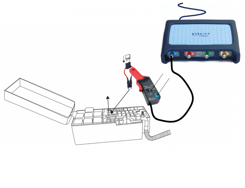
View connection guidance notes.
Note
The orientation of the amp clamp relative to the wire will determine whether it has a positive or negative output. If a live waveform does not appear on your screen, or appears to be inverted, try reversing the orientation of the clamp.

This known good waveform has the following characteristics:
Go to the drop-down menu bar at the lower left corner of the Waveform Library window and select Fuel pump current.
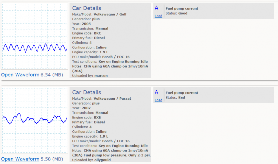

If you zoom in on the waveform you can see the pump waveform in even more detail. It shows a current pulse for each sector of the commutator. The majority of fuel pumps have 6 to 8 sectors. Our example has 8, but if you are unsure you can count the pulses quickly and easily in PicoScope 6.
By using the vertical rulers you can mark the waveform where the pattern appears to be repeated.
Align the two rulers at this point and apply the Falling Edge Measurement. This will reveal the number of sectors present on the commutator.
With the rulers aligned you can also use the Frequency and RPM indicator which will indicate the speed of the fuel pump. In this example, the measured speed is 8190 RPM.
A known good fuel pump waveform will generally have a seesaw pattern with relative consistency and minimal variation between the highs and lows. This can make it difficult to find the number of sectors on the commutator. A bad waveform will show large or irregular drops in the pattern, with large differences between the highs and lows. These obvious inconsistencies can help identify a worn spot on the commutator or a short in the armature.
When you have a fuel pump issue you will experience loss of power. The pump may still pressurize the system and the engine may even start, but when the demand from the fuel pump is high, there will be a distinct lack of power. This can be down to a number of issues: there could be a blockage in the fuel lines, the fuel filter could be blocked or the non-return valve could no longer be operating correctly. A repeated feature on the waveform can indicate wear and an impending failure.
Time rulers used to mark sections on the commutator.
Frequency and RPM indicator measurement taken between the rulers
Reference waveform from known good fuel pump
Our waveform in Figure 4 shows a very uneven current draw on a number of sections when compared to a known good reference waveform from the waveform library. (Click here for more information regarding reference waveforms.)
This issue could be down to a poor conducting commutator or worn bushes. We would normally expect a current draw from this type of pump to be around 2.5 A, but the above waveform is above 0.5 A. From what we can see there is enough evidence to warrant removing the pump for further investigation.
GT032
Disclaimer
This help topic is subject to changes without notification. The information within is carefully checked and considered to be correct. This information is an example of our investigations and findings and is not a definitive procedure.
Pico Technology accepts no responsibility for inaccuracies. Each vehicle may be different and require unique test
settings.
We know that our PicoScope users are clever and creative and we’d love to receive your ideas for improvement on this test. Click the Add comment button to leave your feedback.


