PicoScope 7 Automotive
Available for Windows, Mac, and Linux, the next evolution of our diagnostic scope software is now available.
Automotive guided tests
Library of examples on how to perform tests when using PicoScope.

Training
Our collection of training videos, articles, guides and information on training courses.

Waveform library
The Waveform Library is a global database of waveforms uploaded by PicoScope users.

Case studies
Real-life case studies show how the professionals use PicoScope to diagnose vehicle faults.

A to Z of PicoScope
Detailed description of various PicoScope software and hardware features.

Videos
Training resources and demonstrations on PicoScope and the Automotive Diagnostics Kit.

Newsletter
Archive of our monthly Automotive Newsletters.

Documentation
Download manuals, brochures, posters, and training materials.

Reviews and awards
Accolades for the preferred diagnostic tool for service centers and vehicle manufacturers.


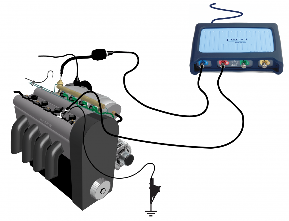
FirstLook Engine Diagnostic Sensor

Secondary ignition pickup (capacitive with BNC)
*At Pico we are always looking to improve our products. The tools used in this guided test may have been superseded and the products above are our latest versions used to diagnose the fault documented in this case study.
The purpose of this test is to assess fuel injector activity using the First Look sensor by measuring fuel pressure regulator diaphragm fluctuations with the engine at idle.
WARNING
Uninsulated HT pickups are designed to clip around double-insulated HT leads only – they are not designed for direct connection to a hazardous live voltage.
To prevent injury or death, when connecting or disconnecting an HT pickup:
View connection guidance notes.
These waveforms have the following characteristics:
Go to the drop-down menu bar at the lower left corner of the Waveform Library window and select, Fuel pressure regulator pressure waveform.

The fuel rail acts as a fuel reservoir to supply the injectors in a multi-point injection system. The fuel rail pressure regulator acts to adjust the fuel rail pressure according to the intake manifold vacuum at its vacuum connection.
With this system, changes in pressure on the vacuum side of the regulator’s diaphragm induce changes in pressure on the fuel rail side. Conversely, changes in fuel rail pressure, for example from injector opening and closing, can affect the air pressure on the vacuum side of the regulator diaphragm.
Therefore, by removing the vacuum connection to the regulator, we can use the First Look pressure sensor to measure air pressure pulsations caused by rail pressure pulsations as the injectors open and close. Note that the First Look sensor output is not an actual measure of pressure but is a representation of component/pressure activity and used, in this case, for comparative purposes.
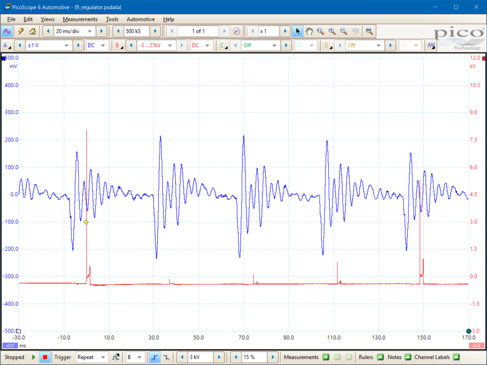
Waveform features
When an injector opens, fuel and pressure are lost from the fuel rail. This produces the first negative peak at the start of each pulsation event.
The action of the fuel pump causes a volume of fuel to flow into the rail and replace the injected fuel. Once the fuel volume has been replaced, the fuel’s inertia causes a rail pressure overshoot seen as the first positive pulse within each pulsation.
The remaining, decaying, oscillations result from complex fluid dynamic reactions as the fuel flow stabilises, and as the injector closes.
With constant engine operating conditions, the pulsations should start at precisely regular intervals and have equal peak to peak amplitudes.
The pulsations will occur in cylinder firing order.
Waveform diagnosis
A comparison of the initial peak to peak amplitudes across all pulsations will indicate whether the injectors are functioning equally and in a timely manner.
As the pulsations occur in cylinder firing order (in a sequential multi-point injection system), the cylinder number 1 reference (Channel B) allows us to identify which pulsation belongs to which cylinder’s injector.
In the example above, the pulsations are timely but the peak to peak amplitude of the first pulsation is lower than those in the next three pulsations.
As the test engine was a conventional 4-cylinder four stroke, with a 180° crank throw, a firing order 1-3-4-2, and sequential injection on its intake stroke, it is possible to identify the problem injector:
Ignition sparks are normally timed to occur at a crank angle Before Top Dead Centre (BTDC) on the respective cylinder’s compression stroke. The cylinder that is on its intake stroke whilst cylinder 1 is on its compression stroke is the cylinder that follows cylinder number 1 in the firing order. Therefore, the example waveforms are indicating that there is a problem with fuel injection on cylinder number 3.
Typical symptoms that might arise from injector faults are:
Injector, or related, faults can be:
GT132
Disclaimer
This help topic is subject to changes without notification. The information within is carefully checked and considered to be correct. This information is an example of our investigations and findings and is not a definitive procedure.
Pico Technology accepts no responsibility for inaccuracies. Each vehicle may be different and require unique test
settings.
We know that our PicoScope users are clever and creative and we’d love to receive your ideas for improvement on this test. Click the Add comment button to leave your feedback.


