PicoScope 7 Automotive
Available for Windows, Mac, and Linux, the next evolution of our diagnostic scope software is now available.
Automotive guided tests
Library of examples on how to perform tests when using PicoScope.

Training
Our collection of training videos, articles, guides and information on training courses.

Waveform library
The Waveform Library is a global database of waveforms uploaded by PicoScope users.

Case studies
Real-life case studies show how the professionals use PicoScope to diagnose vehicle faults.

A to Z of PicoScope
Detailed description of various PicoScope software and hardware features.

Videos
Training resources and demonstrations on PicoScope and the Automotive Diagnostics Kit.

Newsletter
Archive of our monthly Automotive Newsletters.

Documentation
Download manuals, brochures, posters, and training materials.

Reviews and awards
Accolades for the preferred diagnostic tool for service centers and vehicle manufacturers.


Passive scope probe 100 MHz
*At Pico we are always looking to improve our products. The tool used in this guided test may have been superseded and the product above is our latest version used to diagnose the fault documented in this case study.
The purpose of this test is to verify the integrity of the FlexRay networks by checking the mirror image nature of the signals and the coincidence of the edges.
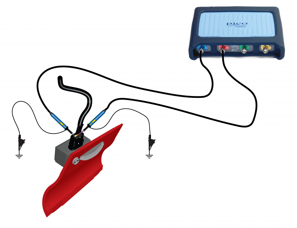
View connection guidance notes.
Note
The BNC-to-4-mm cables that are used for normal signals are not suitable. For high-speed signals like those used on the FlexRay network, you must use high-speed probes.
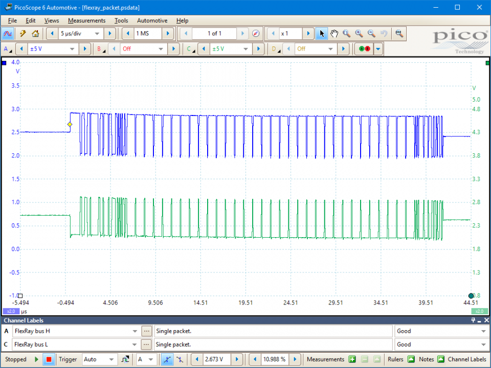
The above FlexRay waveform is a detail zoom of the FlexRay message and allows the individual state changes to be viewed. This enables the mirror image nature of the signals, and the coincidence of the edges to be verified.
Here we can see clearly that the signals are equal and opposite, and that they are of the same amplitude. The edges are clean and coincident with each other. This shows that the FlexRay network is enabling communication between the nodes and the FlexRay controller unit. This test effectively verifies the integrity of the bus at this point in the FlexRay network, and if a particular ECU (node) is not responding correctly, the fault is likely to be the ECU itself. The rest of the bus should work correctly.
It may be necessary to check the condition of the signals present at the connector of each of the ECUs on the FlexRay network as a final check. The data at each node will always be the same on the same bus. Remember that much of the data on the network is safety critical, so DO NOT use insulation piercing probes on FlexRay lines!
FlexRay is a fast, deterministic and fault-tolerant bus system for automotive use.
The FlexRay® protocol answers that demand with a high speed, deterministic and fault tolerant communications technology. Designed specifically for in-vehicle networking, FlexRay won't replace existing networks, but instead it will work in conjunction with already well-established systems, such as the controller area network (CAN), local interconnect network (LIN) and media oriented systems transport (MOST).
An in-vehicle network with FlexRay serving as the backbone provides determinism for engine control and fault tolerance for steer-by-wire, brake-by-wire and other advanced safety applications.
In FlexRay, the cycle period is divided into two parts: One static, for time-critical messages, and one dynamic, for less important messages. The static part is time-triggered whereas the dynamic part is event-triggered. For example, a node transmitting messages to the brakes would be in the static part whereas a node transmitting information to the audio system would be in the dynamic part.
FlexRay - compared to CAN - offers a significantly greater bandwidth of 10 Mbit/s.
GT125-2
Disclaimer
This help topic is subject to changes without notification. The information within is carefully checked and considered to be correct. This information is an example of our investigations and findings and is not a definitive procedure.
Pico Technology accepts no responsibility for inaccuracies. Each vehicle may be different and require unique test
settings.
We know that our PicoScope users are clever and creative and we’d love to receive your ideas for improvement on this test. Click the Add comment button to leave your feedback.
Ian Crane
December 22 2018
I do not see the configuration of the high speed probe as being at all suitable for automotive use. This is a hand held lab scope probe, might be electrically suitable but not physically suitable


