PicoScope 7 Automotive
Available for Windows, Mac, and Linux, the next evolution of our diagnostic scope software is now available.
Automotive guided tests
Library of examples on how to perform tests when using PicoScope.

Training
Our collection of training videos, articles, guides and information on training courses.

Waveform library
The Waveform Library is a global database of waveforms uploaded by PicoScope users.

Case studies
Real-life case studies show how the professionals use PicoScope to diagnose vehicle faults.

A to Z of PicoScope
Detailed description of various PicoScope software and hardware features.

Videos
Training resources and demonstrations on PicoScope and the Automotive Diagnostics Kit.

Newsletter
Archive of our monthly Automotive Newsletters.

Documentation
Download manuals, brochures, posters, and training materials.

Reviews and awards
Accolades for the preferred diagnostic tool for service centers and vehicle manufacturers.


20 A / 60 A DC (low amps) current clamp

200 A / 2000 A (high amps) DC current clamp

Back-pinning Probe Set

Flexible Back-pinning Probe

Large Dolphin/Gator Clips
*At Pico we are always looking to improve our products. The tools used in this guided test may have been superseded and the products above are our latest versions used to diagnose the fault documented in this case study.
The purpose of this test is to investigate the engine coolant cooling fan operation by monitoring the control unit signal and motor current draw through varying fan speeds.

View connection guidance notes.

Warning
Note
The orientation of the current clamp relative to the wire will determine whether it has a positive or negative output. If a live waveform does not appear on your screen, or appears to be inverted, try reversing the orientation of the clamp.

The example connection was made on a BMW vehicle. This system varies the fan speed by a change in duty cycle of the signal. The fan is at rest at 10% and at maximum speed at 90%. The fan or fans have a constant-voltage supply with the earth return path being switched though the vehicle's electronic control unit (ECM).
Go to the drop-down menu bar at the lower left corner of the Waveform Library window and select, cooling fan current or cooling fan voltage.


Many motor vehicle manufacturers now use variable-speed engine cooling fans within their model ranges. The advantage of a variable-speed engine cooling fan is that the engine is better able to control its operating temperature under varying conditions. The cooling fan's speed reduces as the vehicles road speed increases, because a larger volume of air naturally passes through the radiator. There may also be an input into the vehicle's electronic control module (ECM) from the vehicle's climate control unit.
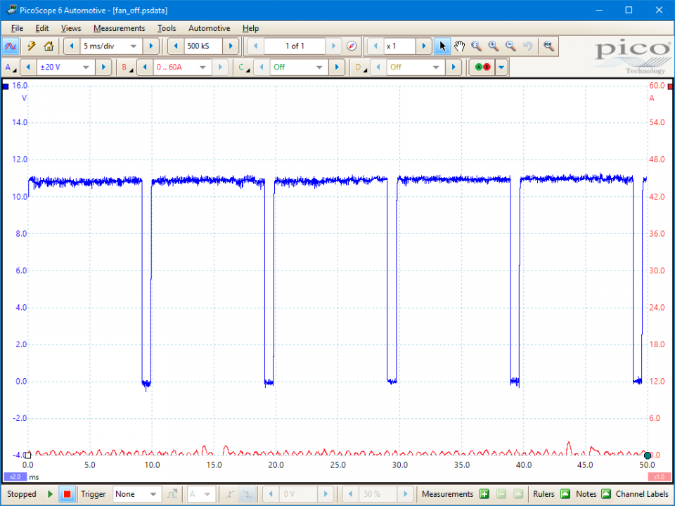
The signal (blue trace) shows the cooling fan's earth return as a 0 to 12 volt square wave that is modulated at a frequency of 110 Hz. The ECM adjusts the fan's speed by altering the square wave's pulse width.
A signal that has a lower duty cycle (on-time) results in a slower fan speed and as the duty cycle increases, the fan speed also increases.
The current draw on the fan is measured using the amps clamp. The current draw is approximately 50 amps when the fan is running at full speed. The current waveform is shown in the red trace in Figure 3.
Depending on the manufacturer, the fan or fans may continue to run after the ignition has been switched off until the engines reaches a predefined temperature.
Ensure that the fan operates at varying speeds by monitoring the duty cycle on the cooling fan's earth return. This can be monitored using either an oscilloscope or a multimeter set to dwell. If the fan's duty cycle fails to increase with increasing engine temperature, the vehicle's ECM needs to be tested by a specialist to ensure that this function is working.
Operate the climate control and ensure that the duty cycle increases. The increase in duty cycle is required to pull more cool air through the air con's condenser, located in front of the radiator.
Note: Before condemning any of the vehicle's components, ensure that the particular model has the function being tested as there is a wide variation between both manufacturers and individual models.
The connections to test this fan on a BMW vehicle were made at the multi-plug by the top of the radiator cowling. The three wires were: power supply (red/blue), an earth (brown) and the signal from the ECM (yellow/red).
GT071
Disclaimer
This help topic is subject to changes without notification. The information within is carefully checked and considered to be correct. This information is an example of our investigations and findings and is not a definitive procedure.
Pico Technology accepts no responsibility for inaccuracies. Each vehicle may be different and require unique test
settings.
We know that our PicoScope users are clever and creative and we’d love to receive your ideas for improvement on this test. Click the Add comment button to leave your feedback.


