PicoScope 7 Automotive
Available for Windows, Mac, and Linux, the next evolution of our diagnostic scope software is now available.
Automotive guided tests
Library of examples on how to perform tests when using PicoScope.

Training
Our collection of training videos, articles, guides and information on training courses.

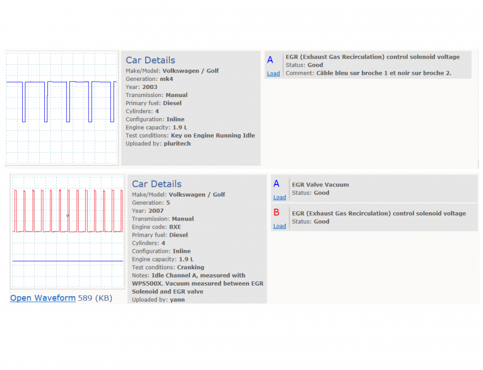
Waveform library
The Waveform Library is a global database of waveforms uploaded by PicoScope users.

Case studies
Real-life case studies show how the professionals use PicoScope to diagnose vehicle faults.

A to Z of PicoScope
Detailed description of various PicoScope software and hardware features.

Videos
Training resources and demonstrations on PicoScope and the Automotive Diagnostics Kit.

Newsletter
Archive of our monthly Automotive Newsletters.

Documentation
Download manuals, brochures, posters, and training materials.

Reviews and awards
Accolades for the preferred diagnostic tool for service centers and vehicle manufacturers.


Back-pinning Probe Set

Flexible Back-pinning Probe

PicoScope Battery Clip

Premium Test Leads: Set of four leads 3 m (TA125 - TA128)
*At Pico we are always looking to improve our products. The tools used in this guided test may have been superseded and the products above are our latest versions used to diagnose the fault documented in this case study.
The purpose of this test is to examine the control signal voltage at the Exhaust Gas Recirculation (EGR) vacuum solenoid valve during engine hot run conditions.
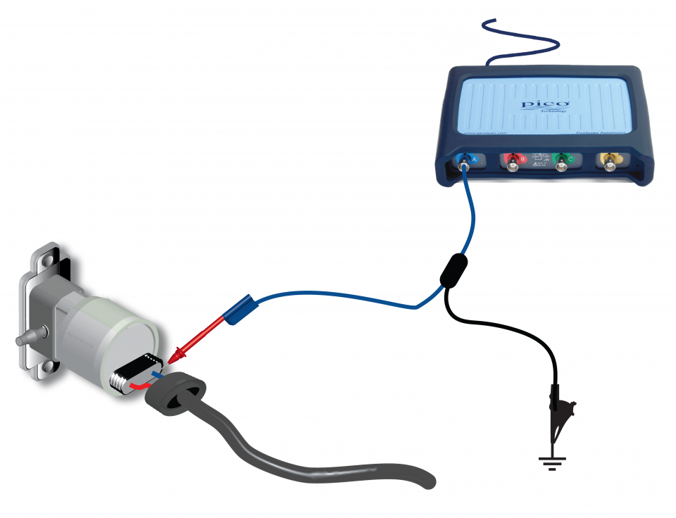
View connection guidance notes.
Note
The solenoid has two terminals, both will show the circuit supply voltage at ignition on.
The switching frequency is dependent on system variations at the time of testing. These variations will not be the same across different manufacturers.
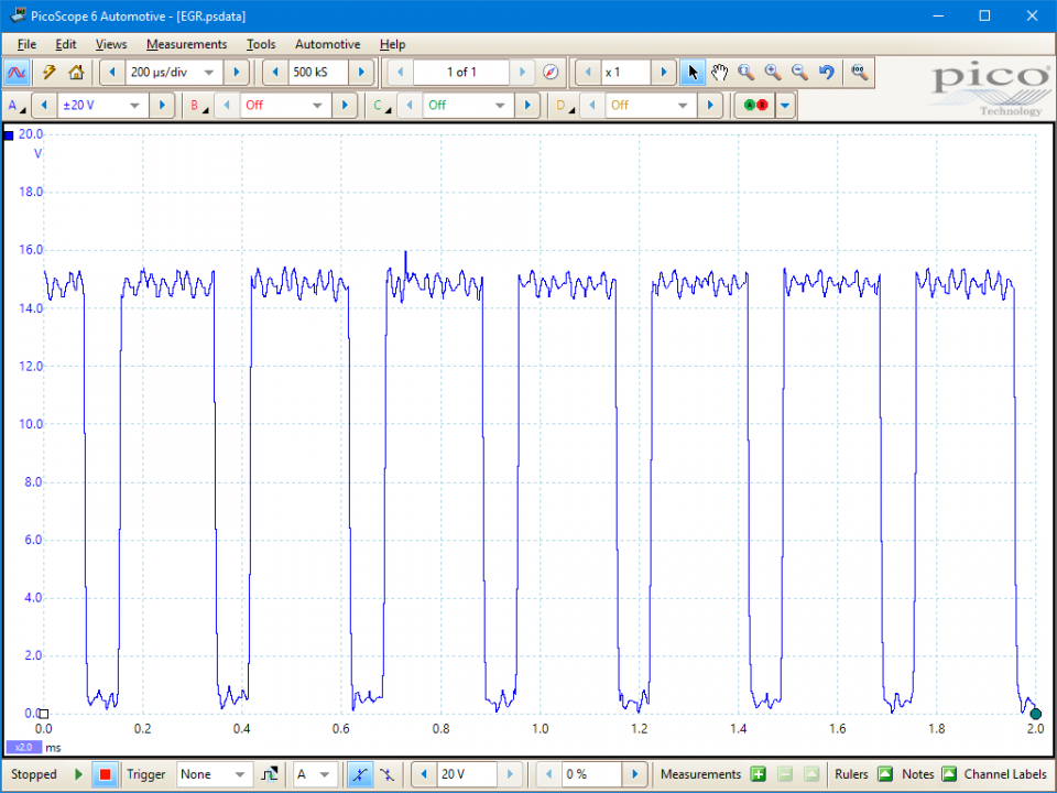
This known good waveform has the following characteristics:
Go to the drop-down menu bar at the lower left corner of the Waveform Library window and select, EGR (Exhaust Gas Recirculation) control solenoid voltage


The function of Exhaust Gas Recirculation (EGR) is to lower the oxides of nitrogen (NOx) under certain circumstances. As the internal combustion temperature rises, the nitrogen within the air/fuel mixture starts to oxidise causing NOx to be produced. While this burning is less than desired, it is inevitable as the air/fuel ratio is increased and a weaker mixture is ignited.
The NOx output is at a maximum when the engine has reached its normal operating temperature and the vehicle is subjected to light throttle or light load conditions.
The catalytic converter is designed to eradicate the majority of the NOx by neutralising it when it comes into contact with the precious metal rhodium, but by reducing the NOx before it reaches the catalytic converter ensures even lower outputs. The EGR valve allows a small amount of the exhaust gases to 'bleed' back into the inlet manifold to lower the combustion temperature and reduce the chances of the nitrogen burning. The EGR valve is a small mechanical device that allows the passage of exhaust gas when it receives a vacuum supply.
This supply is governed by a vacuum switch which in turn is activated by a signal from the Electronic Control Module (ECM). NOx, like hydrocarbons, is measured in parts per million and the reading recorded in a workshop environment is significantly lower to that recorded when the vehicle is at cruise..
EGR taken to excess can affect combustion and increase hydrocarbons. It is therefore necessary to monitor the amount of exhaust gas that enters the inlet manifold. Different manufacturers perform this task in different ways, and some general examples of this are described below.
Honda use an ECM containing a programmed map. The map contains information on the correct amount of EGR according to factors such as: engine speed, road speed, temperature and load.
Under the right conditions for EGR to take place, the ECM earths the path of the solenoid valve and this allows a vacuum source to operate the EGR valve. The EGR valve also includes a lift sensor, a similar device to a throttle potentiometer. It has a 5-volt supply, earth and variable signal back to the ECM depending on the position of the EGR valve. If the amount of exhaust gas passing through the valve exceeds the parameters in the ECM's map, the ECM shuts the solenoid valve by removing its earth path. This making and breaking, or 'pulsing', of the earth path allows fine adjustments to be made ensuring precise control of EGR.
GM/Vauxhall/Opel have a similar system, but the solenoid valve, lift sensor and the EGR valve are all one unit. Fault-finding is also made harder by the fact that EGR takes places inside the cylinder head through a passage connecting the exhaust and inlet manifolds.
Ford, as always, have some interesting names and acronyms for the components within their EGR system. To start with, the control solenoid is referred to as an Electronic Vacuum Regulator (EVR) and their method of monitoring the amount of EGR is by a Differential Pressure Feedback Electronic System (DPFE). This pressure difference is then converted into a voltage and sent to the ECM for reference. Again the ECM contains a map for the correct amount of EGR and if this differs the ECM adjusts the control of the EVR to trim the amount of gas passing to the inlet manifold.
Selection of component-related Diagnostic Trouble Codes (DTCs):
P0400 - Exhaust Gas Recirculation Flow Malfunction
P0401 - Exhaust Gas Recirculation (EGR) Flow Insufficient
P0402 - Exhaust Gas Recirculation Flow Excessive Detected
P0403 - Exhaust Gas Recirculation (EGR) Solenoid Control Circuit
P0404 - Exhaust Gas Recirculation (EGR) Open Position Performance
P0405 - Exhaust Gas Recirculation (EGR) Position Sensor Circuit Low Voltage
P0406 - Exhaust Gas Recirculation Sensor A Circuit High
P0407 - Exhaust Gas Recirculation Sensor B Circuit Low
P0408 - Exhaust Gas Recirculation Sensor B Circuit High
P1403 - Exhaust Gas Recirculation System Valve 1
P1404 - Exhaust Gas Recirculation (EGR) Closed Position Performance
P1405 - Exhaust Gas Recirculation System Valve 3
P1406 - EGR Valve Pintle Position Circuit
P1407 - EGR Air Intrusion in Exhaust Supply to EGR Valve
P1409 - EGR Vacuum System Leak
GT031
Disclaimer
This help topic is subject to changes without notification. The information within is carefully checked and considered to be correct. This information is an example of our investigations and findings and is not a definitive procedure.
Pico Technology accepts no responsibility for inaccuracies. Each vehicle may be different and require unique test
settings.
We know that our PicoScope users are clever and creative and we’d love to receive your ideas for improvement on this test. Click the Add comment button to leave your feedback.


