PicoScope 7 Automotive
Available for Windows, Mac, and Linux, the next evolution of our diagnostic scope software is now available.
Automotive guided tests
Library of examples on how to perform tests when using PicoScope.

Training
Our collection of training videos, articles, guides and information on training courses.

Waveform library
The Waveform Library is a global database of waveforms uploaded by PicoScope users.

Case studies
Real-life case studies show how the professionals use PicoScope to diagnose vehicle faults.

A to Z of PicoScope
Detailed description of various PicoScope software and hardware features.

Videos
Training resources and demonstrations on PicoScope and the Automotive Diagnostics Kit.

Newsletter
Archive of our monthly Automotive Newsletters.

Documentation
Download manuals, brochures, posters, and training materials.

Reviews and awards
Accolades for the preferred diagnostic tool for service centers and vehicle manufacturers.


Back-pinning Probe Set

PicoScope Battery Clip

Flexible Back-pinning Probe

Large Dolphin/Gator Clips

Premium Test Lead: BNC to 4 mm, 3 m

Premium Test Leads: Set of four leads 3 m (TA125 - TA128)
*At Pico we are always looking to improve our products. The tools used in this guided test may have been superseded and the products above are our latest versions used to diagnose the fault documented in this case study.
The purpose of this test is to confirm the integrity of the ignition trigger signals sent from the ECOTEC 1.6 Lt. Multec PCM based on the switching voltage and duty present at the ignition amplifier during engine run conditions.
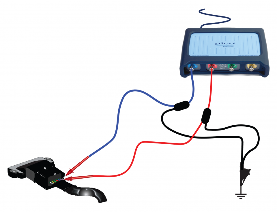
View connection guidance notes.
The double ended coil differs from many other systems as it has the ignition amplifier built into the coil pack. The coil/amplifier pack will have 4 electrical connections. The pack receives a 12 volt supply from the ignition switch, has an independent earth return and the remaining two connections are in the form of a 5 volt 'squarewave' digital signal from the Electronic Control Module (ECM).
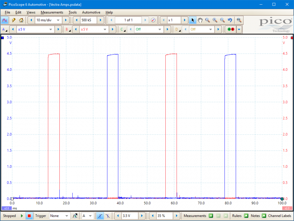
The ECM will receive information from the engine's sensors and calculates the point of ignition by the ECM from its internal pre-set parameter. At the designated point, the 5 volt supply drops to zero volts, signalling the amplifier to remove the earth path on the coil primary, firing the coil.
The coil/amplifier pack has two separate sides (one for cylinders 1 + 4 and the other for cylinders 2 + 3). Using an oscilloscope with dual trace both circuits can be monitored and it can be seen that the coils are fired alternately, as the example shows.
This particular system that is fitted to the 1.6 litre GM/Vauxhall/Opel ECOTEC engine has the ignition amplifier as an integral part of the coil pack.
This particular configuration is a hindrance to those of us who perform diagnostic tuning, as the system does not allow for any connections to the low tension circuit. When the two outer electrical connections are monitored with an oscilloscope a digital square wave is seen and not the expected primary parade picture. The integral coil pack with the built in amplifier will have a voltage supply on the centre terminal at 12 volts with two 5 volt square wave signals to switch the pair of coils.
If the coil's switching is faulty due to a lazy power transistor and the 'normal' induced voltage is reduced, this would, in normal circumstances, be easily seen but with this combination the only clue would be in a reduced spark duration and coil output.

GT042
Disclaimer
This help topic is subject to changes without notification. The information within is carefully checked and considered to be correct. This information is an example of our investigations and findings and is not a definitive procedure.
Pico Technology accepts no responsibility for inaccuracies. Each vehicle may be different and require unique test
settings.
We know that our PicoScope users are clever and creative and we’d love to receive your ideas for improvement on this test. Click the Add comment button to leave your feedback.


