PicoScope 7 Automotive
Available for Windows, Mac, and Linux, the next evolution of our diagnostic scope software is now available.
Automotive guided tests
Library of examples on how to perform tests when using PicoScope.

Training
Our collection of training videos, articles, guides and information on training courses.

Waveform library
The Waveform Library is a global database of waveforms uploaded by PicoScope users.

Case studies
Real-life case studies show how the professionals use PicoScope to diagnose vehicle faults.

A to Z of PicoScope
Detailed description of various PicoScope software and hardware features.

Videos
Training resources and demonstrations on PicoScope and the Automotive Diagnostics Kit.

Newsletter
Archive of our monthly Automotive Newsletters.

Documentation
Download manuals, brochures, posters, and training materials.

Reviews and awards
Accolades for the preferred diagnostic tool for service centers and vehicle manufacturers.


Multimeter Probes

Back-pinning Probe Set

Flexible Back-pinning Probe

PicoScope Battery Clip
*At Pico we are always looking to improve our products. The tools used in this guided test may have been superseded and the products above are our latest versions used to diagnose the fault documented in this case study.
The purpose of this test is to check a distributor pick-up’s Hall effect signal during engine cranking or running conditions.
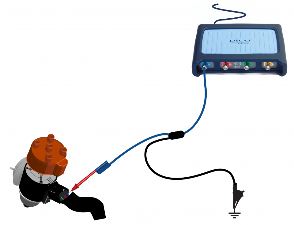
View connection guidance notes.
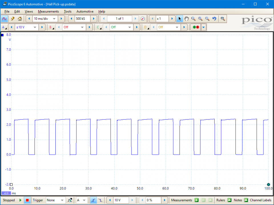
This known good waveform has the following characteristics:

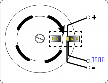
The function of a distributor pick-up is to provide a timing reference signal to the Ignition Control Module (ICM) or Engine Control Module (ECM) to indicate the primary circuit dwell period for each ignition event.
The mechanism uses a rotating assembly consisting of a set of rotating vanes (one for each cylinder) passing between a stationary magnet opposing a stationary Hall sensor. As the vanes pass in and out of the gap, the magnetic field is disturbed. Each disturbance causes the Hall sensor output to switch. Therefore, the sensor output is a digital signal with a low voltage at around 0 V and a high voltage up to the sensor supply voltage. An output around 0 V indicates dwell, or coil on time.
As distributor rotation is mechanically linked to engine rotation, an increase in engine speed reduces the dwell period but the dwell angle remains constant. At increased engine speeds, dwell is advanced by a centrifugal flyweight mechanism within the distributor.
The ICM or ECM, dependent on type, use the Hall sensor output as a (switched-earth) trigger of the primary circuit driver transistor. However, the module retains control of the actual dwell period and other charging parameters, such as current limitation, peak coil charge, and current cut-off.
This additional control ensures that an ignition coil is not overheated by too much dwell or that the spark duration is not reduced by too little dwell. Similarly, the actual dwell period can be increased during cranking to compensate for lower system voltages (to maintain the same overall coil charge).
For engine specific ignition dwell periods, consult manufacturer’s data.
Typical system faults will include:
Mechanical:
Electrical:
These faults would manifest themselves as:
GT020
Disclaimer
This help topic is subject to changes without notification. The information within is carefully checked and considered to be correct. This information is an example of our investigations and findings and is not a definitive procedure.
Pico Technology accepts no responsibility for inaccuracies. Each vehicle may be different and require unique test
settings.
We know that our PicoScope users are clever and creative and we’d love to receive your ideas for improvement on this test. Click the Add comment button to leave your feedback.


