PicoScope 7 Automotive
Available for Windows, Mac, and Linux, the next evolution of our diagnostic scope software is now available.
Automotive guided tests
Library of examples on how to perform tests when using PicoScope.

Training
Our collection of training videos, articles, guides and information on training courses.

Waveform library
The Waveform Library is a global database of waveforms uploaded by PicoScope users.

Case studies
Real-life case studies show how the professionals use PicoScope to diagnose vehicle faults.

A to Z of PicoScope
Detailed description of various PicoScope software and hardware features.

Videos
Training resources and demonstrations on PicoScope and the Automotive Diagnostics Kit.

Newsletter
Archive of our monthly Automotive Newsletters.

Documentation
Download manuals, brochures, posters, and training materials.

Reviews and awards
Accolades for the preferred diagnostic tool for service centers and vehicle manufacturers.


20 A / 60 A DC (low amps) current clamp

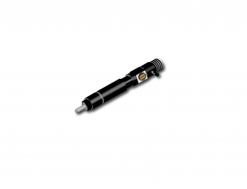
Small Delphi injector connector breakout lead
*At Pico we are always looking to improve our products. The tools used in this guided test may have been superseded and the products above are our latest versions used to diagnose the fault documented in this case study.
The purpose of this test is to check the actuation current within a Delphi-type Common Rail Diesel (CRD) solenoid injector circuit across a range of engine load and demand conditions.
WARNING
This test involves measuring a potentially hazardous voltage.
Please ensure you follow manufacturers' safety instructions and working practices and ensure the rated voltage for all accessories you are using meets or exceeds the expected voltage.
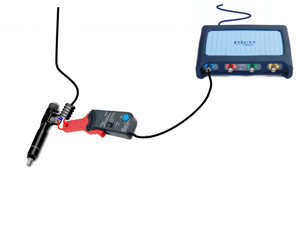
View connection guidance notes.
Note
The orientation of the amp clamp relative to the wire will determine whether it has a positive or negative output. If a live waveform does not appear on your screen, or appears to be inverted, try reversing the orientation of the clamp.
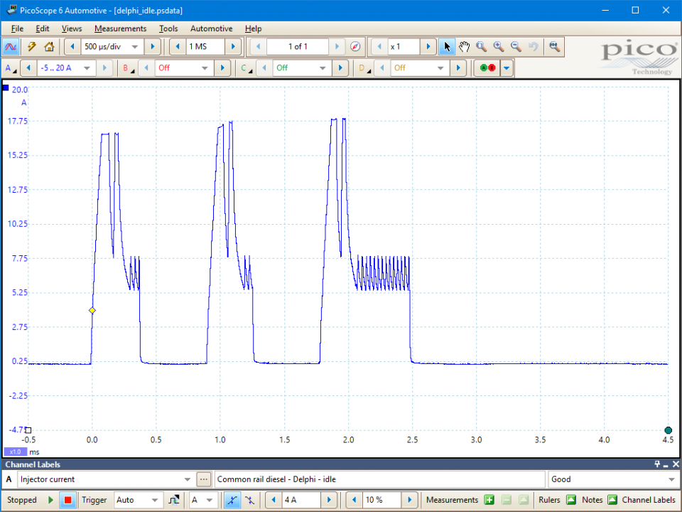
Engine at idle condition
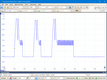
Engine accelerated (increased demand) condition
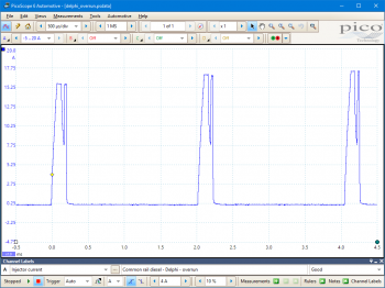
Engine overrun condition
These known good waveforms have the following characteristics:
Note
Under some load and demand conditions, only one pilot injection might be observed (rather than two seen in the examples).
Go to the drop-down menu bar at the lower left corner of the Waveform Library window and select, Injector current.

A common rail diesel injector delivers atomised fuel directly to the combustion chamber.
Injection timing and quantity is controlled by the Engine Control Module (ECM). Common rail diesel solenoid injectors can be actuated independently of the pressure generating mechanism, unlike their counterparts within distributor pump or unit injector (i.e. Pumpe-Düse or PD) systems, which can only operate within periods of high pumping pressure. This characteristic facilitates multiple injection events per engine cycle and permits additional functionality:
In order to facilitate their rapid operation, injector switching circuit voltages are quite high, typically 50 to 90 V.
Furthermore, the injector solenoids are rapidly energised using charge drawn from a combination of the vehicle power supply system and capacitors. The capacitors are charged by the circuit voltage induced by the solenoids when the supply voltage is removed.
Common rail diesel injectors are susceptible to mechanical and electrical faults, producing a variety of symptoms:
Selection of component related Diagnostic Trouble Codes (DTCs):
P0200 – Injector Circuit Malfunction
P0201 – Injector Circuit Malfunction – Cylinder 1
P0202 – Injector Circuit Malfunction – Cylinder 2
P0203 – Injector Circuit Malfunction – Cylinder 3
P0204 – Injector Circuit Malfunction – Cylinder 4
P0205 – Injector Circuit Malfunction – Cylinder 5
P0206 – Injector Circuit Malfunction – Cylinder 6
P0207 – Injector Circuit Malfunction – Cylinder 7
P0208 – Injector Circuit Malfunction – Cylinder 8
P0209 – Injector Circuit Malfunction – Cylinder 9
P0210 – Injector Circuit Malfunction – Cylinder 10
P0211 – Injector Circuit Malfunction – Cylinder 11
P0212 – Injector Circuit Malfunction – Cylinder 12
P0213 – Cold Start Injector 1 Malfunction
P0214 – Cold Start Injector 2 Malfunction
P0216 – Injection Timing Control Circuit Malfunction
P020A – Cylinder 1 Injection Timing
P020B – Cylinder 2 Injection Timing
P020C – Cylinder 3 Injection Timing
P020D – Cylinder 4 Injection Timing
P020E – Cylinder 5 Injection Timing
P020F – Cylinder 6 Injection Timing
P021A – Cylinder 7 Injection Timing
P021B – Cylinder 8 Injection Timing
P021C – Cylinder 9 Injection Timing
P021D – Cylinder 10 Injection Timing
P021E – Cylinder 11 Injection Timing
P021F – Cylinder 12 Injection Timing
P0261 – Cylinder 1 Injector Circuit Low
P0262 – Cylinder 1 Injector Circuit High
P0263 – Cylinder 1 Contribution/Balance Fault
P0264 – Cylinder 2 Injector Circuit Low
P0265 – Cylinder 2 Injector Circuit High
P0266 – Cylinder 2 Contribution/Balance Fault
P0267 – Cylinder 3 Injector Circuit Low
P0268 – Cylinder 3 Injector Circuit High
P0269 – Cylinder 3 Contribution/Balance Fault
P0270 – Cylinder 4 Injector Circuit Low
P0271 – Cylinder 4 Injector Circuit High
P0272 – Cylinder 4 Contribution/Balance Fault
P0273 – Cylinder 5 Injector Circuit Low
P0274 – Cylinder 5 Injector Circuit High
P0275 – Cylinder 5 Contribution/Balance Fault
P0276 – Cylinder 6 Injector Circuit Low
P0277 – Cylinder 6 Injector Circuit High
P0278 – Cylinder 6 Contribution/Balance Fault
P0279 – Cylinder 7 Injector Circuit Low
P0280 – Cylinder 7 Injector Circuit High
P0281 – Cylinder 7 Contribution/Balance Fault
P0282 – Cylinder 8 Injector Circuit Low
P0283 – Cylinder 8 Injector Circuit High
P0284 – Cylinder 8 Contribution/Balance Fault
P0285 – Cylinder 9 Injector Circuit Low
P0286 – Cylinder 9 Injector Circuit High
P0287 – Cylinder 9 Contribution/Balance Fault
P0288 – Cylinder 10 Injector Circuit Low
P0289 – Cylinder 10 Injector Circuit High
P0290 – Cylinder 10 Contribution/Balance Fault
P0291 – Cylinder 11 Injector Circuit Low
P0292 – Cylinder 11 Injector Circuit High
P0293 – Cylinder 11 Contribution/Balance Fault
P0294 – Cylinder 12 Injector Circuit Low
P0295 – Cylinder 12 Injector Circuit High
P0296 – Cylinder 12 Contribution/Balance Fault
GT099
Disclaimer
This help topic is subject to changes without notification. The information within is carefully checked and considered to be correct. This information is an example of our investigations and findings and is not a definitive procedure.
Pico Technology accepts no responsibility for inaccuracies. Each vehicle may be different and require unique test
settings.
We know that our PicoScope users are clever and creative and we’d love to receive your ideas for improvement on this test. Click the Add comment button to leave your feedback.
Ron Mcleod
April 09 2019
I like the example waveforms you include but I would like you to include a waveform of the injector on crank, I think it would be very helpful in a no start situation.


