PicoScope 7 Automotive
Available for Windows, Mac, and Linux, the next evolution of our diagnostic scope software is now available.
Automotive guided tests
Library of examples on how to perform tests when using PicoScope.

Training
Our collection of training videos, articles, guides and information on training courses.

Waveform library
The Waveform Library is a global database of waveforms uploaded by PicoScope users.

Case studies
Real-life case studies show how the professionals use PicoScope to diagnose vehicle faults.

A to Z of PicoScope
Detailed description of various PicoScope software and hardware features.

Videos
Training resources and demonstrations on PicoScope and the Automotive Diagnostics Kit.

Newsletter
Archive of our monthly Automotive Newsletters.

Documentation
Download manuals, brochures, posters, and training materials.

Reviews and awards
Accolades for the preferred diagnostic tool for service centers and vehicle manufacturers.


10:1 Attenuator

Multimeter Probes
*At Pico we are always looking to improve our products. The tools used in this guided test may have been superseded and the products above are our latest versions used to diagnose the fault documented in this case study.
The purpose of this test is to examine both crank sensor and ignition primary voltage as a possible cause of engine misfire at high RPM.
WARNING
This test involves measuring a potentially hazardous voltage.
Please ensure you follow manufacturers' safety instructions and working practices and ensure the rated voltage for all accessories you are using meets or exceeds the expected voltage.

View connection guidance notes.
Note
This helpfile refers to a 10:1 attenuator. If you are using a 20:1 attenuator please adjust the Probe settings for the relevant channel. These settings can be found under the Channel Options button, then: Probe > 20:1 Attenuator.
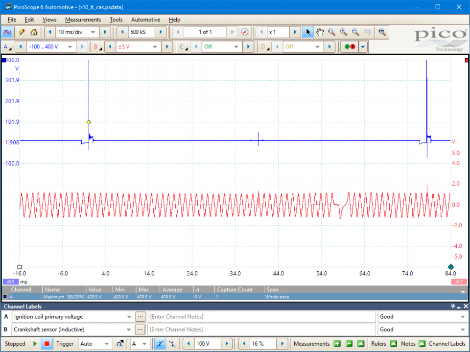
In this waveform we can observe the output voltage from the Crank Angle Sensor (shown in red) at the same time as monitoring the Ignition's Primary trace (shown in blue). The main reason for evaluating these two waveforms together is to identify the cause of any impending misfires at higher engine revs.
The picture shows the 'missing tooth' reference point and the primary induced voltage. The offset between these two points will vary between different vehicle manufacturers as the 'missing tooth' is not always in the same position.
As the engine speed is increased, the distance between the reference point and the induced voltage alters due to the engine's ignition timing advance. The gap in the red trace is due to the 'missing tooth' in the flywheel or reluctor and is used as a reference for the Electronic Control Module (ECM) to ascertain the engine's position. Some systems use one reference point per revolution while others use two. The trace from the crank sensor should maintain a constant voltage at a given engine speed, while the primary ignition trace shows the firing of the ignition circuit.
Should the engine start to misfire at speed, ensure that the crank sensor signal is not breaking down: this may be seen as an intermittent trace or as a reduction in amplitude. If the CAS output remains constant, the primary picture may falter: this could be due to either a fault coil or amplifier.


GT390
Disclaimer
This help topic is subject to changes without notification. The information within is carefully checked and considered to be correct. This information is an example of our investigations and findings and is not a definitive procedure.
Pico Technology accepts no responsibility for inaccuracies. Each vehicle may be different and require unique test
settings.
We know that our PicoScope users are clever and creative and we’d love to receive your ideas for improvement on this test. Click the Add comment button to leave your feedback.


