PicoScope 7 Automotive
Available for Windows, Mac, and Linux, the next evolution of our diagnostic scope software is now available.
Automotive guided tests
Library of examples on how to perform tests when using PicoScope.

Training
Our collection of training videos, articles, guides and information on training courses.

Waveform library
The Waveform Library is a global database of waveforms uploaded by PicoScope users.

Case studies
Real-life case studies show how the professionals use PicoScope to diagnose vehicle faults.

A to Z of PicoScope
Detailed description of various PicoScope software and hardware features.

Videos
Training resources and demonstrations on PicoScope and the Automotive Diagnostics Kit.

Newsletter
Archive of our monthly Automotive Newsletters.

Documentation
Download manuals, brochures, posters, and training materials.

Reviews and awards
Accolades for the preferred diagnostic tool for service centers and vehicle manufacturers.


WPS500X Pressure Transducer Kit (with carry case)

WPS500X Pressure Transducer
*At Pico we are always looking to improve our products. The tools used in this guided test may have been superseded and the products above are our latest versions used to diagnose the fault documented in this case study.
The purpose of this test is to evaluate crankcase pressures during idle conditions using the WPS500X pressure transducer.
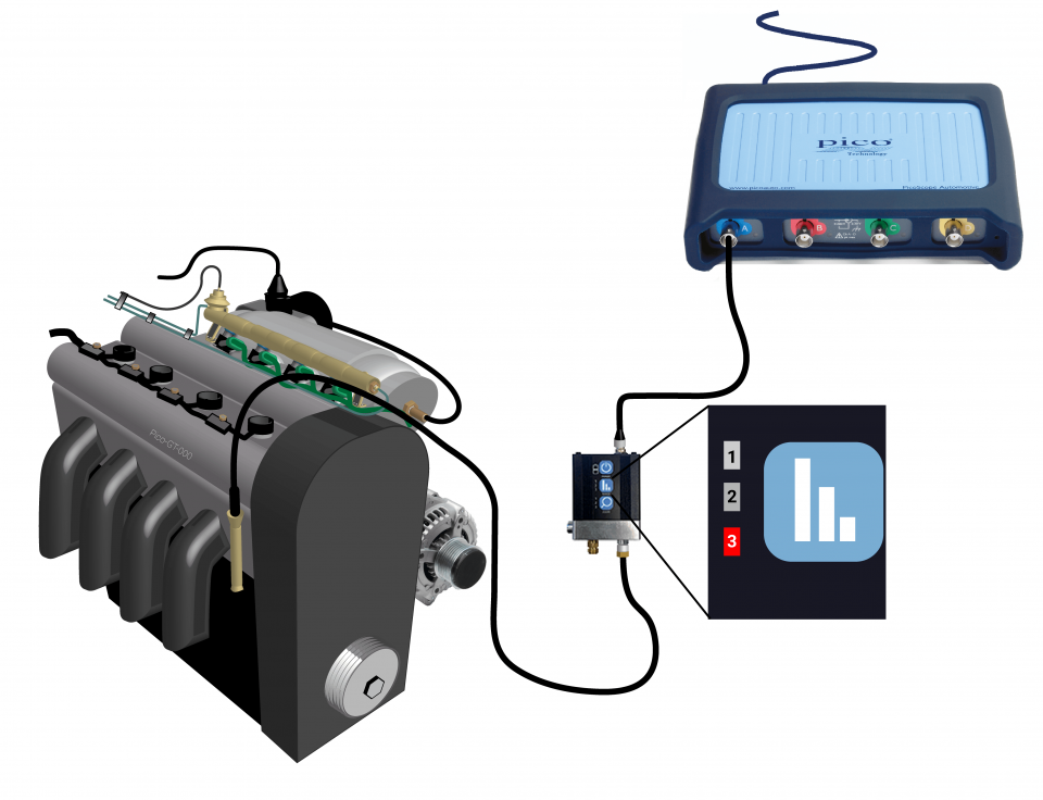
View connection guidance notes.

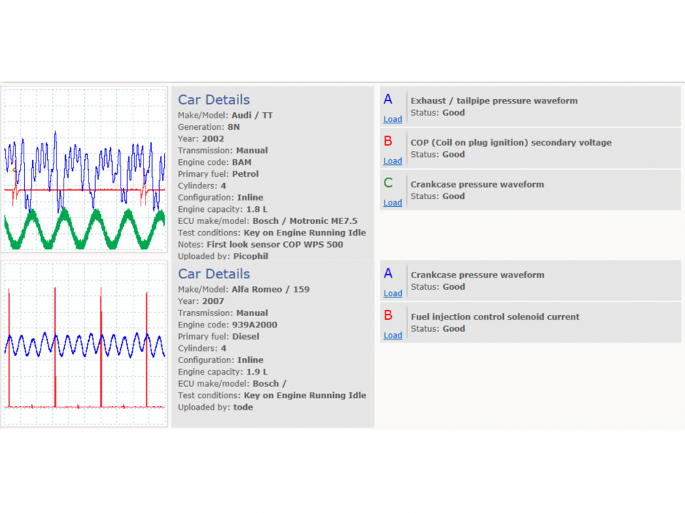
This known good waveform has the following characteristics:
Go to the drop-down menu bar at the lower left corner of the Waveform Library window and select Crankcase pressure waveform.
Combustion gases escape past the piston rings and into the crankcase during an internal combustion engine’s operating cycle. This effect is known as blow-by.
A crankcase ventilation system is used to vent blow-by gases back to the intake manifold, whilst fresh air is drawn in to replace them. This has two effects:
Fresh air enters the crankcase via a breather, which has its inlet close to and downstream of the air filter. A Positive Crankcase Ventilation (PCV) valve regulates the flow of blow-by gases from the crankcase to the intake manifold.
The PCV valve is a normally closed valve. That is, when the engine is off and the crankcase and intake manifold pressures have equalised (with atmospheric pressure), the valve is fully closed. This prevents harmful gases from venting to the atmosphere when the engine if off and the vehicle is stationary.
The higher the crankcase pressure above the intake manifold pressure, the greater the opening of the PCV valve. Therefore, the valve position and gas flow vary with engine operation, as follows:
The measurement of crankcase pressure, usually by connecting at the dipstick tube, breather inlet, or other convenient access point, allows us to assess the degree of blow-by and the operation of the ventilation system.
Waveform features
The crankcase pressure waveform features have the following relationship with engine operation during idle:
Waveform diagnosis
Diagnoses rely mostly on the identification of periodic anomalies within the waveform. An observed anomaly provides sufficient justification for further investigation.
Periodic waveform anomalies will occur if there is:
An overall low crankcase pressure will occur if:
An overall high crankcase pressure will occur if:
A faulty PCV valve or system can affect an engine’s fuel trims and cause either lean or rich running conditions (depending on the fault). In these cases, the engine management system may switch on the MIL light and set a diagnostic trouble code (DTC).
Other related symptoms may include erratic idle/running, oil burning/blue smoke, or the contamination and build-up of carbon, water, or sludge, within the crankcase, breather, PCV valve, and connected systems.
GT894-EN
Disclaimer
This help topic is subject to changes without notification. The information within is carefully checked and considered to be correct. This information is an example of our investigations and findings and is not a definitive procedure.
Pico Technology accepts no responsibility for inaccuracies. Each vehicle may be different and require unique test
settings.
We know that our PicoScope users are clever and creative and we’d love to receive your ideas for improvement on this test. Click the Add comment button to leave your feedback.


