PicoScope 7 Automotive
Available for Windows, Mac, and Linux, the next evolution of our diagnostic scope software is now available.
Automotive guided tests
Library of examples on how to perform tests when using PicoScope.

Training
Our collection of training videos, articles, guides and information on training courses.

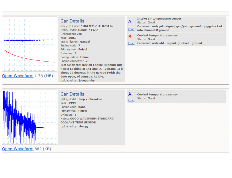
Waveform library
The Waveform Library is a global database of waveforms uploaded by PicoScope users.

Case studies
Real-life case studies show how the professionals use PicoScope to diagnose vehicle faults.

A to Z of PicoScope
Detailed description of various PicoScope software and hardware features.

Videos
Training resources and demonstrations on PicoScope and the Automotive Diagnostics Kit.

Newsletter
Archive of our monthly Automotive Newsletters.

Documentation
Download manuals, brochures, posters, and training materials.

Reviews and awards
Accolades for the preferred diagnostic tool for service centers and vehicle manufacturers.


Multimeter Probes

Back-pinning Probe Set

Flexible Back-pinning Probe

Large Dolphin/Gator Clips
*At Pico we are always looking to improve our products. The tools used in this guided test may have been superseded and the products above are our latest versions used to diagnose the fault documented in this case study.
The purpose of this test is to evaluate the voltage output of an Engine Coolant Temperature (ECT) sensor as the engine coolant temperature increases.

View connection guidance notes.
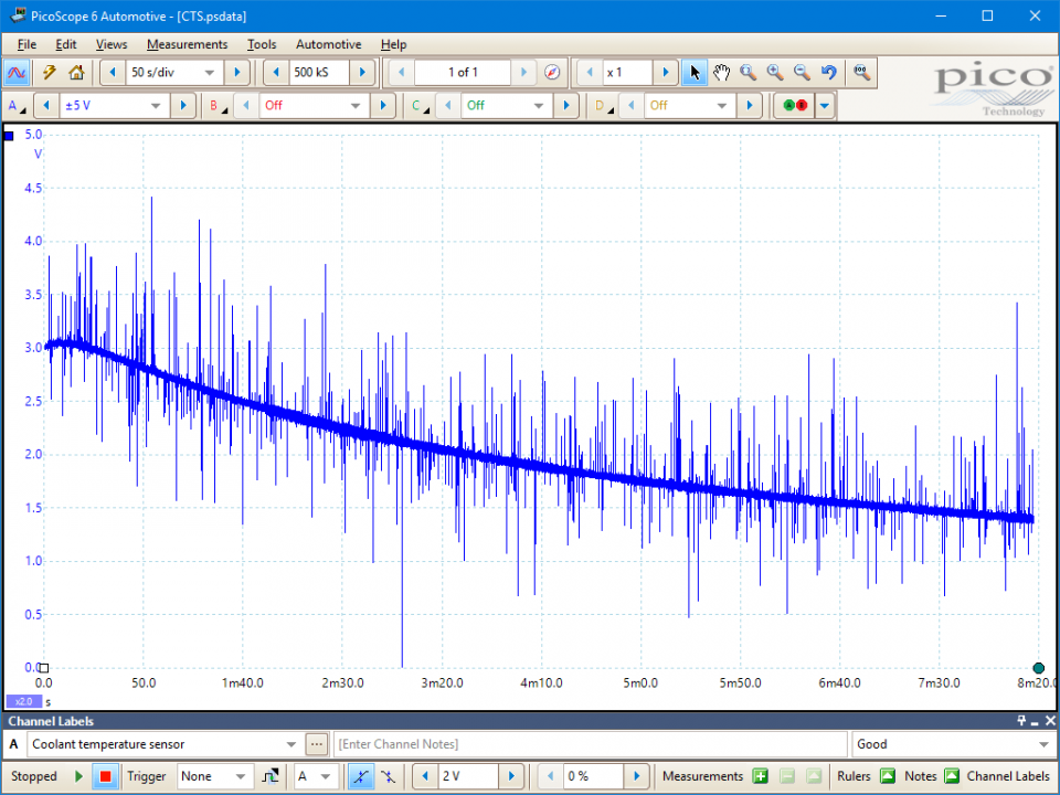
Unfiltered waveform

Waveform filtered with lowpass cut-off at 10 Hz
This known good waveform has the following characteristics:
Go to the drop down menu in the lower left corner of the Waveform Library window and select, Coolant temperature sensor.

An ECT sensor provides a measure of the engine’s coolant temperature to the Engine Control Module (ECM), as part of the engine load sensing apparatus. It is therefore partly responsible for the determination of fuelling, timing and engine speed requirements.
Most ECT sensors have a Negative Temperature Coefficient (NTC) characteristic, meaning their internal resistance decreases as the coolant temperature increases. Therefore, as in the example above, the voltage across an NTC ECT sensor drops as its resistance decreases. A Positive Temperature Coefficient (PTC) sensor will have the opposite behaviour.
ECT sensors are application specific; despite having similar external appearances, their outputs can vary for a given coolant temperature.
An ECM typically estimates engine temperature using multiple parameters, such as initial (prior to start up) ambient air temperature, engine running duration and engine loading. Therefore, a coolant temperature reading on a scan tool, obtained from serial diagnostic data, may be incorrect and may mask the failure of an ECT sensor. For this reason, this type of test is the only reliable way to determine ECT sensor health and function.
The temperature sensor circuits are highly resistance sensitive, requiring a good circuit with clean connectors and no extraneous resistances: any poor/corroded connections will falsify the signal at the ECM, causing the engine to operate out of tolerance.
An ECT circuit might be prone to the typical circuit failures (shorts, open circuits, or high resistances), an internal failure within the sensor, or a failure within the ECM (which otherwise should provide a 5 V reference to the signal wire when the ETC is disconnected).
Typical symptoms of a faulty ECT sensor are:
Selection of component-related Diagnostic Trouble Codes (DTCs):
P0115
P0116
P0117
P0118
P0119
P0125
P1114
P1115
P1116
P1117
P1118
P1119
P1258
View more
GT015
Disclaimer
This help topic is subject to changes without notification. The information within is carefully checked and considered to be correct. This information is an example of our investigations and findings and is not a definitive procedure.
Pico Technology accepts no responsibility for inaccuracies. Each vehicle may be different and require unique test
settings.
We know that our PicoScope users are clever and creative and we’d love to receive your ideas for improvement on this test. Click the Add comment button to leave your feedback.
Colin
March 06 2022
the voltage across an NTC ECT sensor drops as its resistance decreases.


