PicoScope 7 Automotive
Available for Windows, Mac, and Linux, the next evolution of our diagnostic scope software is now available.

Back-pinning Probe Set

Flexible Back-pinning Probe

Small Crocodile/Gator Clips

PicoScope Sprung Hook Probe

Premium Test Lead: BNC to 4 mm, 3 m

Premium Test Leads: Set of four leads 3 m (TA125 - TA128)
*At Pico we are always looking to improve our products. The tools used in this guided test may have been superseded and the products above are our latest versions used to diagnose the fault documented in this case study.
In this example we have chosen to dual-trace the coolant temperature and the intake air temperature but either sensor can be checked on its own if preferred.
Plug a BNC test lead in to Channel A of the scope. Place a small black clip on the lead end with a black moulding (negative) and a Back-pinning Probe onto the end with a red moulding (positive). Place the small black clip on to the motorcycle frame or battery negative, as illustrated in Figure 1. Check the manufacturer's pin data for the fuel injection Electronic Control Module (ECM) coolant temperature sensor connection terminal. Back-probe the correct multiplug pin with the Back-pinning Probe as in Figure 2. Ensure that a good connection is made through to the wire or terminal and the probe has pierced through the wire and plug insulation.
Plug a BNC test lead in to Channel B of the scope. Place a Back-pinning Probe onto the end with a red moulding (positive). Piggyback the black moulded end of the BNC test lead (negative) on to the connection already made to either the motorcycle frame or battery negative, as illustrated in Figure 3. Check the manufacturer's pin data for the fuel injection Electronic Control Module (ECM) intake air temperature sensor connection terminal. Back-probe the correct multiplug pin with the Back-pinning Probe as in Figure 2. Ensure that a good connection is made through to the wire or terminal and the probe has pierced through the wire and plug insulation.
With the example waveform displayed on the screen you can now hit the space bar to start looking at live readings.
In this particular waveform we can observe the reducing voltage of the coolant temperature sensor (Channel A) as the motorcycle warms up from initial start-up. We can also observe the voltage of the intake air temperature sensor (Channel B). The motorcycle was left to run during the test with increased idle via the handlebar choke control. Some motorcycles will not have this control as they employ an idle speed control or thermostatic choke device.
The Coolant Temperature Sensor (CTS) is a small two-connection device that has the function of reporting the engine's temperature back to the Engine Control Module (ECM). It is this signal that determines the engine's warm-up enrichment and the engine's fast idle speed, should an idle speed control device be fitted. This sensor normally has a Negative Temperature Coefficient (NTC), which means that the component's resistance drops as the temperature rises. A Positive Temperature Coefficient (PTC) sensor is not as common as the NTC and its resistance reacts to temperature in the opposite way.

After testing the dash display showed 80 C.
The sensors are manufacturer-specific and, although they may look identical, their outputs vary dramatically.
The Air Temperature Sensor (ATS) is a thermistor, situated in the induction air flow, whose resistance generally decreases with increasing air temperature. Of the overall temperature correction, the ATS contributes only 20% while the coolant temperature sensor provides the other 80%.

After testing, the dash display showed 19 C.
Should there appear to be a fault whilst testing at the ECM, the next course of action is to locate either sensor using manufacturer's data. Naturally the coolant temperature sensor is mounted on the engine and the intake air temperature sensor somewhere in the induction system. As this may involve removing the motorcycle's fairings, all tests are initially performed at the ECM.
Once located, either sensor can be tested at its own multiplug connection to ensure there is no fault in the wiring loom. The sensor's resistance may also be tested with a multimeter and compared to manufacturer's data.
Should there be the need to remove the coolant temperature sensor from the engine, the motorcycle is left to cool down and any pressure is released from the coolant system.
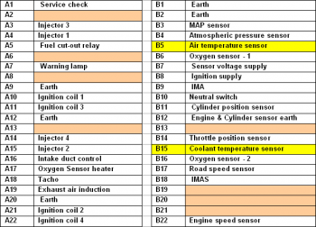
Our test vehicle was a Honda motorbike. Below is the ECM multiplug pin data. Pin data is manufacturer- and model-specific and this data is shown for illustration purposes only.


AT106-2
Disclaimer
This help topic is subject to changes without notification. The information within is carefully checked and considered to be correct. This information is an example of our investigations and findings and is not a definitive procedure.
Pico Technology accepts no responsibility for inaccuracies. Each vehicle may be different and require unique test
settings.
We know that our PicoScope users are clever and creative and we’d love to receive your ideas for improvement on this test. Click the Add comment button to leave your feedback.