PicoScope 7 Automotive
Available for Windows, Mac, and Linux, the next evolution of our diagnostic scope software is now available.
Automotive guided tests
Library of examples on how to perform tests when using PicoScope.

Training
Our collection of training videos, articles, guides and information on training courses.

Waveform library
The Waveform Library is a global database of waveforms uploaded by PicoScope users.

Case studies
Real-life case studies show how the professionals use PicoScope to diagnose vehicle faults.

A to Z of PicoScope
Detailed description of various PicoScope software and hardware features.

Videos
Training resources and demonstrations on PicoScope and the Automotive Diagnostics Kit.

Newsletter
Archive of our monthly Automotive Newsletters.

Documentation
Download manuals, brochures, posters, and training materials.

Reviews and awards
Accolades for the preferred diagnostic tool for service centers and vehicle manufacturers.


WPS500X Pressure Transducer

Vacuum hose

Universal vacuum adaptor

BNC to BNC Cable with Earth Clamp
*At Pico we are always looking to improve our products. The tools used in this guided test may have been superseded and the products above are our latest versions used to diagnose the fault documented in this case study.
The purpose of this test is to evaluate each common rail diesel injector’s contribution to back-leakage pressure, for low return pressure systems only, using WPS500X
Injector back-leakage can also be referred to as injector spill testing or leak-off testing.
Note: Diesel injector back-leakage, pressure and balance are dependent on fuel quality, the integrity of the high-pressure diesel pump priming circuit, the common rail high-pressure circuit, the engine load, and the common rail diesel control system/components.
All the below values obtained with the WPS500X are referenced to gauge pressure (0 mbar at atmospheric pressure).
All the numerical readings quoted in this help topic are typical and are not applicable to all common rail systems.
Make sure that the WPS500X is fully charged before you start the test.
|
Accessories
|
PicoScope settings
|
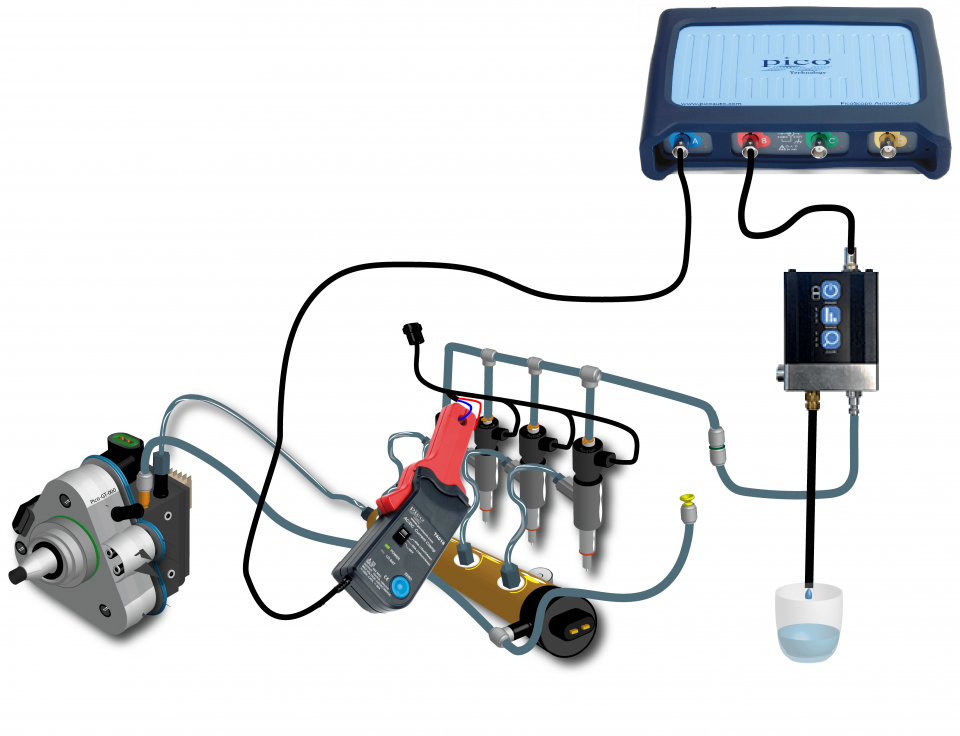
The WPS500X pressure transducer requires a single connection to the spill pipework, at the point where all injector back-leakage returns to the fuel tank. All injector leak-off will, therefore, pass through the WPS500X pressure transducer en route to a collection bottle.
We advise that you recharge your WPS500X after each use to ensure it is ready for future measurements.
All the values included in the example waveforms are typical, and are not specific to all engine styles.
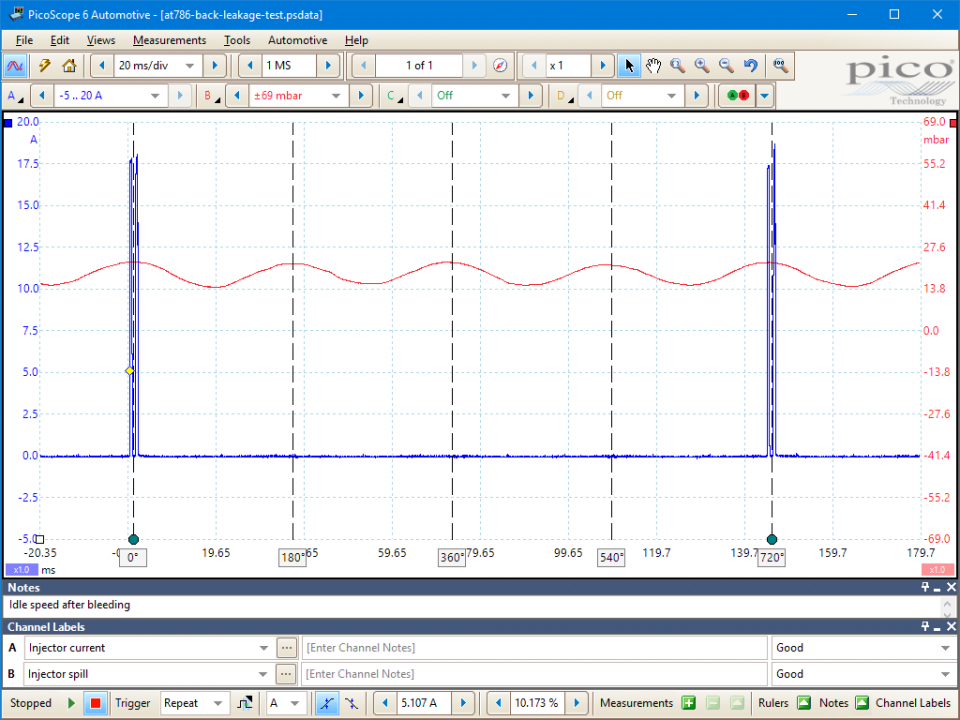
hannel A, Blue (1, 3, 4, 2, and 1) indicate the current drawn by injector 1 and the position of the remaining injection events taking place during two complete revolutions of the crankshaft. (The time taken to complete the 4-stroke cycle at an idle speed of 800 rpm is approximately 150 ms.)
Note: the firing order may change for the vehicle under test.
The engine tested above utilizes the firing order 1, 3, 4, 2.
Figure 2:
A denotes atmospheric pressure of 0 mbar.
B indicates the peak back-leakage pressure and pulsations resulting from “leak-off” contributions of each injector (approximately 25 mbar).
Figure 3:
B indicates the highest back-leakage pulsation magnified 1000 times (contributed by injector no. 3). The waveform no longer represents the back-leakage pressure value (see Diagnosis section below).
1 indicates the lowest back-leakage pulsation belonging to injector 2.
When selecting ZOOM LEVEL 3 of your WPS500X, the back-leakage pressure value obtained in Example waveform 1 (25 mbar) is centered around the 0 mbar marker (black dotted line) and no longer represents the pressure value. Zoom level 3 now amplifies the dynamic fluctuations within the back-leakage pressure signal, by magnifying the pulsations 1000 times. This lets you analyze the waveform for irregularities attributed to injector malfunction. While the vehicle tested above did not exhibit any running issues, there is a clear difference in contribution (at idle speed) to back-leakage pulsations between injectors 2 and 3.
Refer to vehicle technical data for specific test conditions and results.
Typical values with an engine at correct operating temperature, idling and no load applied.
Note: Back-leakage pressure and pulsations will change in relation to engine speed and load. Analyse back-leakage pulsations and pressure under conditions equal to the ones reported by the customer.
Engine idling ZOOM OFF (Figure 2)
It is vitally important that all air is bled from the spill hoses and the WPS500X pressure transducer before you analyze the waveform for irregularities. With the engine at the correct operating temperature, you can carry out numerous momentary Wide Open Throttle (WOT) snap tests to purge the air from the injector back-leakage circuit as well as the WPS500X pressure transducer.
When the engine idle speed is stabilized and all loads applied to the engine have settled, you can measure the maximum peak back-leakage pressure (approximately 25 mbar in the example above).
When the engine idle speed is stabilized and all loads applied to the engine have settled, you can measure the maximum peak back-leakage pressure (approximately 25 mbar in the example above).
Note: An increase in common rail pressure will be accompanied by an increase in back-leakage pressure.
Peak back-leakage pressure may vary depending on the system under test. Typical values average between 20 to 300 mbar.
Peak back-leakage pressure may vary depending on the system under test. Typical values average between 20 to 300 mbar.
Symptoms of hesitation at high engine load will be accompanied by a momentary increase in back-leakage pressure and individually deformed pulsations.
Engine idling Zoom level 3 (Figure 3)
While peak back-leakage pressure is important, you can use the zoom function of the WPS500X, with the firing order, to reveal the origin of uneven pulsations in the back-leakage waveform.
You can identify the source of the pulsations by selecting ZOOM LEVEL 3 (press the ZOOM button 3 times on the front panel of the WPS500X). This has the effect of magnifying the pulsations in the back-leakage waveform only. These are formed by leak-off contributions from each injector. Do not refer to the pressure scale on the scope when you use the zoom function, as only the pulsations are displayed on the screen, not the back-leakage pressure value.
With the pulsations magnified like this, you can analyze the formation of each peak for uniformity and balance between peaks.
Peaks that are unevenly formed, or exhibit an irregular shape, indicate a potential injector failure due to internal sticking or worn components. Pulsations with amplitude high above other injectors indicate an injector that is contributing an increased amount of back-leakage in comparison to others. Equally, pulsations with an amplitude below other injectors indicate an injector with a reduced contribution to back-leakage and so a potential blockage or sticking components in the injector.
When you attempt to identify an offending injector due to irregularities in the magnified back-leakage pulsations, use the injection events on channel A of your oscilloscope.
Injector back-leakage pulsations are created during, or shortly after, the main injection event. Looking at Figure 2 and 3, the pulsations for each injector occurs directly above each injection event.
By using the Rotation markers to denote 0 and 720 degree rotation between switching events in injector 1, with four rotation partition rulers to divide the 720 degree rotation into 180 degree intervals, we can reveal the approximate position of the remaining injection events that take place during two full revolutions of the crankshaft (720 degrees).
You can now identify every injector back-leakage pulsation by using the firing order 1, 3, 4, 2 to identify offending injectors.
Alignment of the back-leakage pulsations to each injection event will vary from system to system. To confirm a suspect pulsation (and so an injector), you can introduce a misfire with a Cylinder Cut feature in a scan tool, or substitute an injector with a load box. This will remove the back-leakage contribution for the injector that has been cut and confirm if it is the offending injector.
You can read more about Back-leakage testing in our online training section.
GT786-2
Disclaimer
This help topic is subject to changes without notification. The information within is carefully checked and considered to be correct. This information is an example of our investigations and findings and is not a definitive procedure.
Pico Technology accepts no responsibility for inaccuracies. Each vehicle may be different and require unique test
settings.
We know that our PicoScope users are clever and creative and we’d love to receive your ideas for improvement on this test. Click the Add comment button to leave your feedback.
MikeW
December 10 2018
Hi Ruzsa János, thank you for your observation. We have removed all reference to piezo injectors from this test.
Ruzsa János (Autonet)
March 22 2018
Hi,
this is again a GREAT test - but there is a risk of destroying the Bosch piezo injectors during the measuring.
You write at the beginning: “Solenoid and Piezo type injectors with accessible spill return”. Unfortunatelly, by the Bosch piezo injectors there is a (normally 10 bar) pressure valve in the return circuit, so the injector backflow MUST be hold at 10 bar, otherwise the injectors will stop working in a short time. This is caused by the injectors nternal structure. A stopped injector can be repaired, but only on a test bench.
As the pressure valve is normally part of the return pipe (the connectors to the injector, the connection pipes, the main pipe, the valve and the pipe which goes to the return, in general is not easy to do this measuring, as You HAVE TO make the measuring between the injectors and the return pressure valve . Case the WPS500 is connected in this place with a “T”, the bleeding button may NOT be depressed, and in the measuring range should be the -1,5…13,8 bar


