PicoScope 7 Automotive
Available for Windows, Mac, and Linux, the next evolution of our diagnostic scope software is now available.
Automotive guided tests
Library of examples on how to perform tests when using PicoScope.

Training
Our collection of training videos, articles, guides and information on training courses.

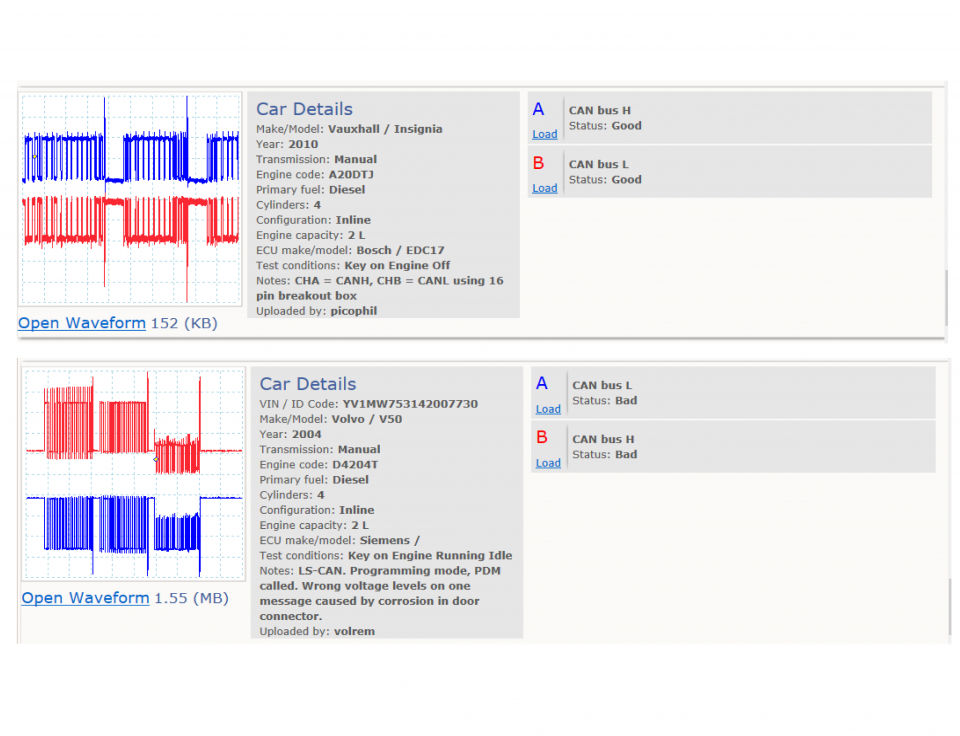
Waveform library
The Waveform Library is a global database of waveforms uploaded by PicoScope users.

Case studies
Real-life case studies show how the professionals use PicoScope to diagnose vehicle faults.

A to Z of PicoScope
Detailed description of various PicoScope software and hardware features.

Videos
Training resources and demonstrations on PicoScope and the Automotive Diagnostics Kit.

Newsletter
Archive of our monthly Automotive Newsletters.

Documentation
Download manuals, brochures, posters, and training materials.

Reviews and awards
Accolades for the preferred diagnostic tool for service centers and vehicle manufacturers.


Back-pinning Probe Set

Flexible Back-pinning Probe

Complete 6-way universal breakout lead kit

Multimeter Probes

CAN Test Box

Shrouded to Unshrouded Adaptor
*At Pico we are always looking to improve our products. The tools used in this guided test may have been superseded and the products above are our latest versions used to diagnose the fault documented in this case study.
The purpose of this test is to determine the physical integrity of a Controller Area Network (CAN) bus by checking its low (CAN-L) and high (CAN-H) line voltages.
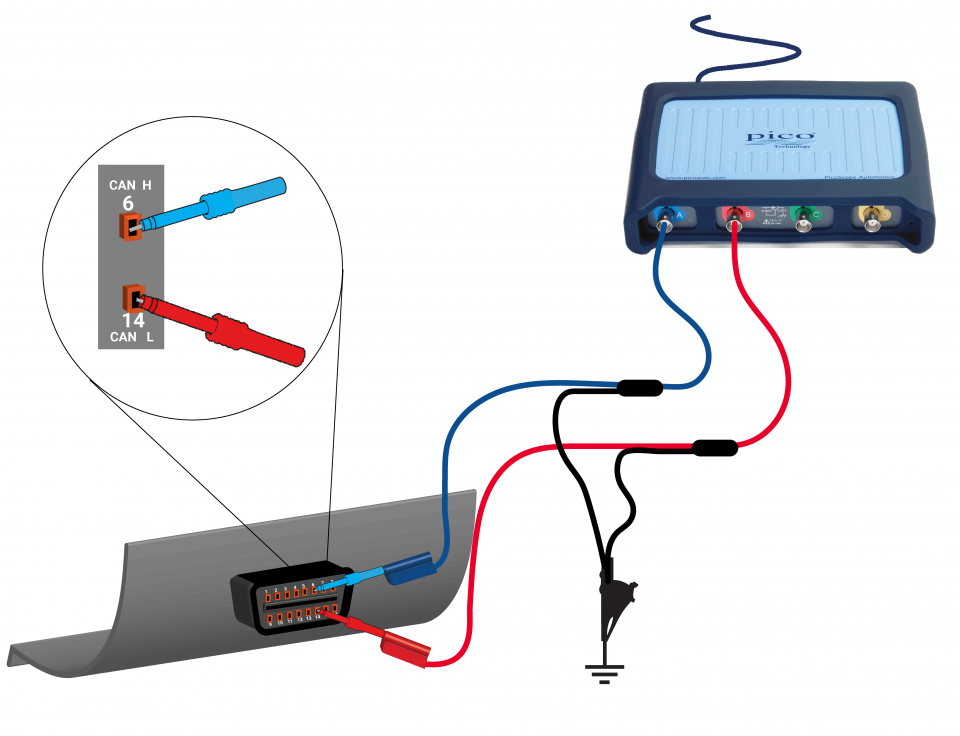
View connection guidance notes.
Notes
If waveforms do not appear on the screen, the DLC may not provide direct access to a CAN bus. Use manufacturer data to identify appropriate access at other locations.
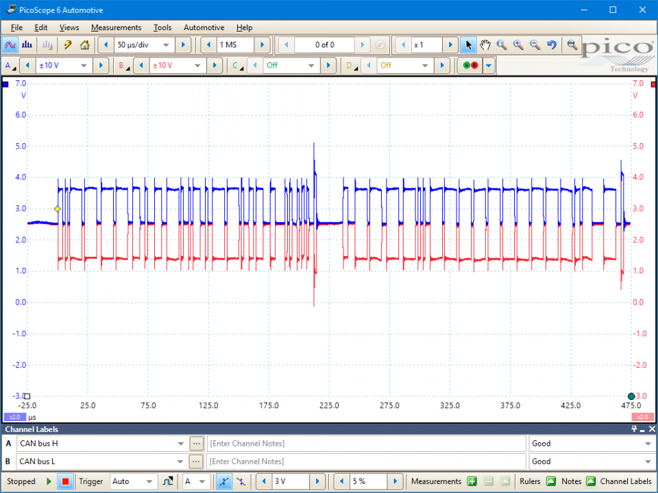
These known good waveforms have the following characteristics:
Go to the drop-down menu bar at the lower left corner of the Waveform Library window and select CAN bus H or CAN bus L.
A CAN bus provides serial communication between control units. For example, a powertrain CAN bus allows an ABS control unit to broadcast a message containing wheel speed data simultaneously to the Engine Control Module (ECM), Transmission Control Module (TCM), Instrument Cluster (IC), and Supplementary Restraint System (SRS).
CAN messages are transmitted digitally as a series of low or high values within a fixed structure known as a frame. The smallest data unit within these binary encoded messages is a bit, logically representing either 0 or 1. A message identifier follows the start of the frame. The identifier assists message arbitration when two or more control units try to broadcast a message at the same time; the lower the identifier’s value, the higher the message’s priority. Various values, including the data payload, and a checksum follow the identifier.
When a control unit receives a message, it calculates a checksum from the data payload and compares it to the value broadcast within the message. If the two are equal, the message is valid. The receiving control unit confirms this by transmitting an acknowledgement during the penultimate bit of the message broadcast. Therefore, the broadcaster will know if a control unit has received an invalid message.
CAN buses are either low or high speed; low speed buses communicate at a fixed rate up to 125 kbit/s, whereas high speed buses communicate at a fixed rate up to 1 Mbit/s. A variant, CAN FD, communicates at variable rates up to 12 Mbit/s. The application determines the bus speed. For example, safety critical powertrain CAN buses require real time communication and are always high speed, typically operating at a rate of 500 kbit/s.
CAN gateways connect buses of different speeds or types. For example, an IC might act as an interface between the powertrain and convenience CAN buses to provide, amongst other things, automatic door locking functionality; e.g. a vehicle speed message from the ABS control unit on the higher speed bus can be transmitted to the convenience control unit on the lower speed bus via the IC. The convenience control module would then know to lock the doors once a certain speed has been reached.
Gateways can also control diagnostic access. When present, diagnostic testers must establish communication with the gateway via the DLC. The gateway then passes diagnostic messages between the tester and the other control units. The tester does not have direct access to the other CAN buses or their messages. Furthermore, it will not be possible to use the DLC as an access point to test CAN bus integrity. Alternative test locations must be identified.
The voltage difference between the CAN-L and CAN-H lines represents the bus’s logical state. Therefore, the lines are referenced to each other rather than to an external potential, such as the chassis ground. This differential arrangement improves noise rejection as interference affects the lines equally and their voltage difference is maintained. Typically, the lines are configured as twisted pairs to reduce interference effects.
On some CAN buses, where the attached control units share a common reference potential (e.g. the chassis ground), the CAN controllers can switch to single line operation to provide fault tolerance in the event of an open circuit on either the CAN-L or CAN-H lines.
High speed CAN buses use terminating resistors to remove transmission reflections within the bus; without the resistors, transmissions can bounce back from the end points and distort the messages. Typically, a 120 ohm resistor is used to connect the CAN-L and CAN-H lines within the two control units at each end of the bus. In this parallel configuration, the total resistance between the CAN-L and CAN-H lines is around 60 ohms. Therefore, measurement of this resistance will indicate the bus’s integrity. Resistance measurements must not be performed on buses without termination resistors, unless all the attached control units have been previously disconnected.
CAN bus faults can cause many symptoms. Typically, they are characterized by a partial or total loss of vehicle or system functionality or a visual or audible warning to the vehicle operator.
CAN buses can be prone to circuit faults, such as:
Similarly, the connected control units can be susceptible to faults with their:
GT126-EN
Disclaimer
This help topic is subject to changes without notification. The information within is carefully checked and considered to be correct. This information is an example of our investigations and findings and is not a definitive procedure.
Pico Technology accepts no responsibility for inaccuracies. Each vehicle may be different and require unique test
settings.
We know that our PicoScope users are clever and creative and we’d love to receive your ideas for improvement on this test. Click the Add comment button to leave your feedback.
chau
April 05 2019
Two complete CAN messages, with each having a more pronounced voltage at the end.
Can you explain me about it? thanks bro


