PicoScope 7 Automotive
Available for Windows, Mac, and Linux, the next evolution of our diagnostic scope software is now available.
Automotive guided tests
Library of examples on how to perform tests when using PicoScope.

Training
Our collection of training videos, articles, guides and information on training courses.

Waveform library
The Waveform Library is a global database of waveforms uploaded by PicoScope users.

Case studies
Real-life case studies show how the professionals use PicoScope to diagnose vehicle faults.

A to Z of PicoScope
Detailed description of various PicoScope software and hardware features.

Videos
Training resources and demonstrations on PicoScope and the Automotive Diagnostics Kit.

Newsletter
Archive of our monthly Automotive Newsletters.

Documentation
Download manuals, brochures, posters, and training materials.

Reviews and awards
Accolades for the preferred diagnostic tool for service centers and vehicle manufacturers.


Multimeter Probes

Back-pinning Probe Set

PicoScope Battery Clip
*At Pico we are always looking to improve our products. The tools used in this guided test may have been superseded and the products above are our latest versions used to diagnose the fault documented in this case study.
The purpose of this test is to evaluate the operation of a Hall effect Camshaft Position (CMP) sensor from its output voltage.
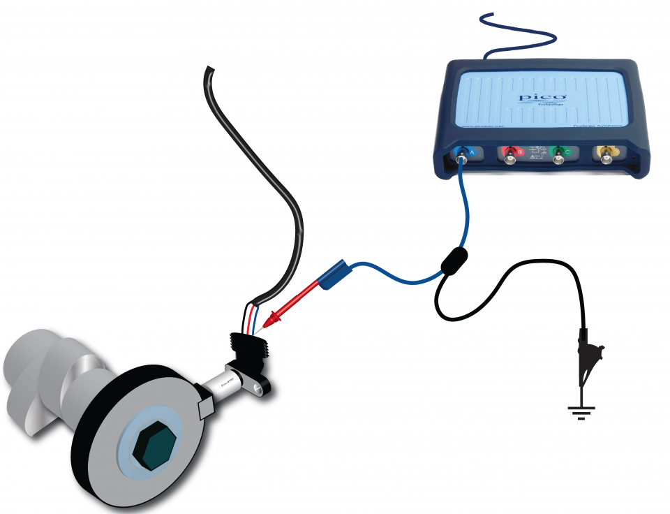
View connection guidance notes.
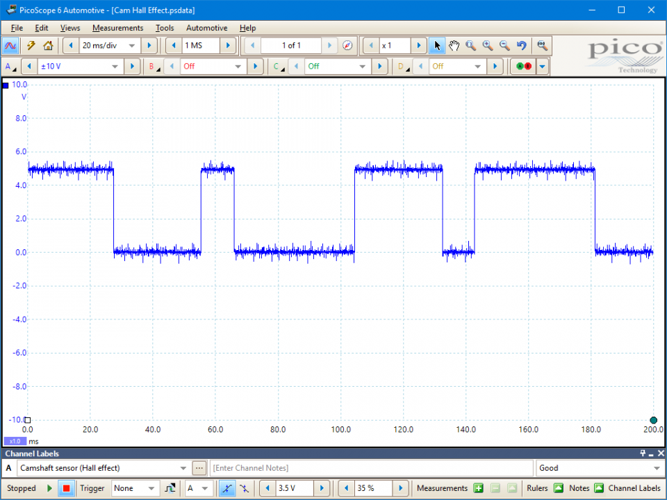
This known good waveform has the following characteristics:
Go to the drop-down menu bar at the lower left corner of the Waveform Library window and select, Camshaft sensor (Hall effect).


A CMP sensor signals one or more fixed camshaft reference positions to the Engine Control Module (ECM), for example, the arrival of a cylinder’s intake stroke. The ECM uses the camshaft sensor signal for accurate timing control of ignition (if a gasoline engine), injection, and variable valve phasing, etc.
As their name implies, Hall effect CMP sensors use the Hall effect, which produces a potential difference (known as the Hall voltage) across the width of a conductor, when it has a current flowing through its length and a magnetic field is applied perpendicular to the current (i.e. through the bottom-top direction of the conductor). When the current is fixed, the greater the magnetic field strength, the greater the Hall effect voltage.
The sensors have in-built conditioning circuits that convert the Hall voltage to a stable digital signal output switching between 0 V and 5 V. As they consume power, Hall effect CMP sensors require voltage feed and earth circuits.
The sensors are accompanied by a pulse wheel. As the pulse wheel rotates, it passes through and disturbs the sensor’s magnetic field to modulate the Hall voltage. In response, the digital sensor output switches either from low to high (0 V to 5 V) or high to low (5 V to 0 V), depending on the sensor circuitry. The overall frequency of the signal will depend on the camshaft speed.
The pulse wheel can have unique patterns for each cylinder, just a single pulse, or something in between. With unique patterns for each cylinder, the CMP sensor signal can be used in a rapid start process. For example, a 4-cylinder engine can start within 180 degrees of crankshaft rotation (90 degrees of camshaft rotation). In these applications, a CMP sensor may be referred to as a Cylinder Identification (CID) sensor or phase sensor and the pulse wheel may be referred to as a phase wheel.
The CMP sensor signal can be critical to ECM operation and failures can cause symptoms such as:
Related failures are:
Selection of component related Diagnostic Trouble Codes (DTCs):
P0340 : Camshaft Position Sensor A - Circuit Malfunction (Bank 1)
P0341 : Camshaft Position Sensor A - Circuit Range/Performance (Bank 1)
P0342 : Camshaft Position Sensor A - Circuit Low Input (Bank 1)
P0343 : Camshaft Position Sensor A - Circuit High Input (Bank 1)
P0344 : Camshaft Position Sensor A - Circuit Intermittent (Bank 1)
P0345 : Camshaft Position Sensor A - Circuit Malfunction (Bank 2)
P0346 : Camshaft Position Sensor A - Circuit Range/Performance (Bank 2)
P0347 : Camshaft Position Sensor A - Circuit Low Input (Bank 2)
P0348 : Camshaft Position Sensor A - Circuit High Input (Bank 2)
P0349 : Camshaft Position Sensor A - Circuit Intermittent (Bank 2)
P0365 : Camshaft Position Sensor B - Circuit Malfunction (Bank 1)
P0366 : Camshaft Position Sensor B - Circuit Range/Performance (Bank 1)
P0367 : Camshaft Position Sensor B - Circuit Low Input (Bank 1)
P0368 : Camshaft Position Sensor B - Circuit High Input (Bank 1)
P0369 : Camshaft Position Sensor B - Circuit Intermittent (Bank 1)
P0390 : Camshaft Position Sensor B - Circuit Malfunction (Bank 2)
P0391 : Camshaft Position Sensor B - Circuit Range/Performance (Bank 2)
P0392 : Camshaft Position Sensor B - Circuit Low Input (Bank 2)
P0393 : Camshaft Position Sensor B - Circuit High Input (Bank 2)
P0394 : Camshaft Position Sensor B - Circuit Intermittent (Bank 2)
GT061
Disclaimer
This help topic is subject to changes without notification. The information within is carefully checked and considered to be correct. This information is an example of our investigations and findings and is not a definitive procedure.
Pico Technology accepts no responsibility for inaccuracies. Each vehicle may be different and require unique test
settings.
We know that our PicoScope users are clever and creative and we’d love to receive your ideas for improvement on this test. Click the Add comment button to leave your feedback.


