PicoScope 7 Automotive
Available for Windows, Mac, and Linux, the next evolution of our diagnostic scope software is now available.
Automotive guided tests
Library of examples on how to perform tests when using PicoScope.

Training
Our collection of training videos, articles, guides and information on training courses.

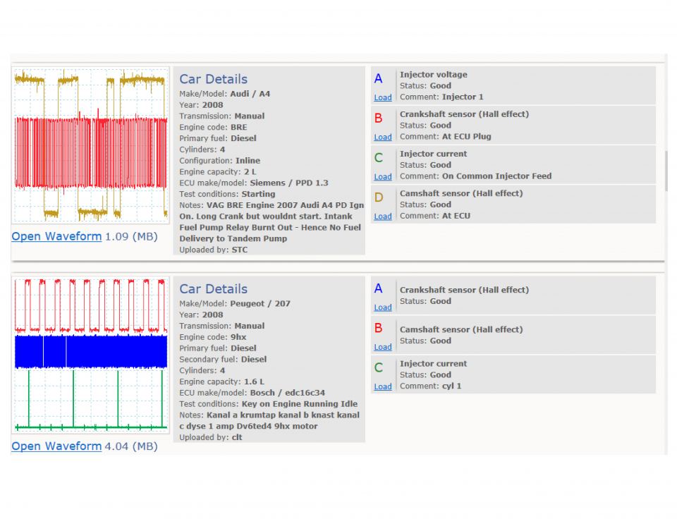
Waveform library
The Waveform Library is a global database of waveforms uploaded by PicoScope users.

Case studies
Real-life case studies show how the professionals use PicoScope to diagnose vehicle faults.

A to Z of PicoScope
Detailed description of various PicoScope software and hardware features.

Videos
Training resources and demonstrations on PicoScope and the Automotive Diagnostics Kit.

Newsletter
Archive of our monthly Automotive Newsletters.

Documentation
Download manuals, brochures, posters, and training materials.

Reviews and awards
Accolades for the preferred diagnostic tool for service centers and vehicle manufacturers.


Multimeter Probes

Back-pinning Probe Set

Flexible Back-pinning Probe

PicoScope Battery Clip
*At Pico we are always looking to improve our products. The tools used in this guided test may have been superseded and the products above are our latest versions used to diagnose the fault documented in this case study.
The purpose of this test is to directly compare the relative positions of the Crankshaft position (CKP) and Camshaft position (CMP) sensor waveforms and features.
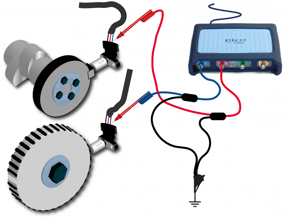
View connection guidance notes.

These known good waveforms have the following characteristics:
Go to the drop-down menu bar at the lower left corner of the Waveform Library window and select Crankshaft sensor (Hall effect) or Camshaft sensor (Hall effect).


An engine’s CKP and CMP sensors provide the Engine Control Module (ECM) with critical engine speed, position, and timing reference data.
For the engine to function properly, the engine must be timed correctly and the sensors and related apparatus must be fixed in the correct position relative to the crankshaft and camshaft(s).
The measurements in this test allow you to directly compare CKP and CMP sensor waveforms, for example, to check that their positions are fixed, and not moving, relative to each other. The measurements can also be compared to manufacturer data or to known good CKP/CMP sensor waveforms (such as those found within the PicoScope Waveform Library).
PicoScope’s Rulers and Measurements tools enable you to identify in degrees (or the number of teeth) between the relative positions of CKP and CMP reference marks.
You may need to check the individual CKP and CMP sensors are functioning correctly before performing the comparisons in this test. Equally, your system may be fitted with other variations of these timing sensors. In which case, we provide Guided tests to show you how to obtain waveforms from them:
Any misalignment of the crankshaft and camshaft sensors, or related components, can cause symptoms, such as:
Related failures are:
Selection of component related Diagnostic Trouble Codes (DTCs):
P0335
P0336
P0337
P0338
P0339
P0340
P0341
P0342
P0343
P0344
P0345
P0346
P0347
P0348
P0349
P0365
P0366
P0367
P0368
P0369
P0390
P0391
P0392
P0393
P0394
View more
GT151
Disclaimer
This help topic is subject to changes without notification. The information within is carefully checked and considered to be correct. This information is an example of our investigations and findings and is not a definitive procedure.
Pico Technology accepts no responsibility for inaccuracies. Each vehicle may be different and require unique test
settings.
We know that our PicoScope users are clever and creative and we’d love to receive your ideas for improvement on this test. Click the Add comment button to leave your feedback.


