PicoScope 7 Automotive
Available for Windows, Mac, and Linux, the next evolution of our diagnostic scope software is now available.
Automotive guided tests
Library of examples on how to perform tests when using PicoScope.

Training
Our collection of training videos, articles, guides and information on training courses.

Waveform library
The Waveform Library is a global database of waveforms uploaded by PicoScope users.

Case studies
Real-life case studies show how the professionals use PicoScope to diagnose vehicle faults.

A to Z of PicoScope
Detailed description of various PicoScope software and hardware features.

Videos
Training resources and demonstrations on PicoScope and the Automotive Diagnostics Kit.

Newsletter
Archive of our monthly Automotive Newsletters.

Documentation
Download manuals, brochures, posters, and training materials.

Reviews and awards
Accolades for the preferred diagnostic tool for service centers and vehicle manufacturers.


Back-pinning Probe Set

Multimeter Probes

Large Dolphin/Gator Clips
*At Pico we are always looking to improve our products. The tools used in this guided test may have been superseded and the products above are our latest versions used to diagnose the fault documented in this case study.
The purpose of this test is to evaluate the operation of the Bosch Common Rail Diesel (CRD) Quantity Control Valve (QCV) based on the voltage and duty control under engine run conditions.
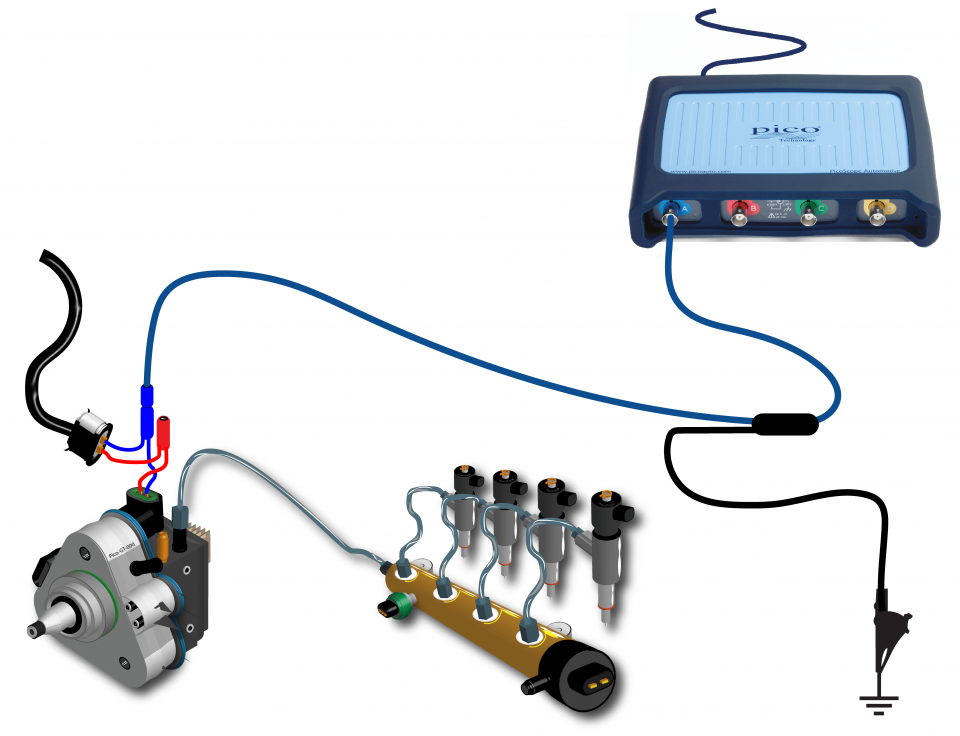
View connection guidance notes.
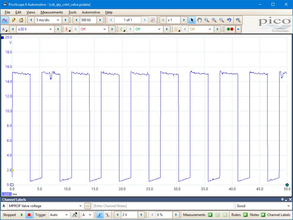
This known good waveform has the following characteristics:
Go to the drop-down menu bar at the lower left corner of the Waveform Library window and select MPROP Valve voltage.

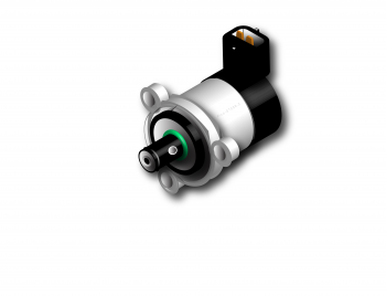
Within a common rail diesel system, the Engine Control Module (ECM) uses a quantity control valve to regulate the fuel pressure entering the common rail via the high pressure pump: when the ECM needs to reduce the pressure, the valve is closed and less fuel is drawn through the pumping mechanism, excess fuel is released to the fuel return system. Conversely, when an increased pressure is needed, the valve is opened and an increased quantity of fuel is delivered through the pump.
A quantity control valve position is determined by the action of a solenoid against a spring. With these devices the valve will move from its default position when current flows through the solenoid. Default may be either open or closed depending on the application. The greater the current, the greater the displacement of the valve. Thus, in some systems an increase in current will cause the valve to become more closed, whereas in others it will cause the valve to become more open.
An ECM can efficiently control current in a circuit using a PWM signal and, for a given electrical load, the greater the duty period, the amount of ON time relative to the whole cycle, the greater the average current flowing through the circuit.
With a switched earth activated circuit, the solenoid is fed with a constant battery positive on both terminals and the ECM controls the path to earth creating current flow. Therefore, the valve is energised on when the actuation signal is at battery negative and de-energised off when the actuation signal is at battery positive. Hence the greater the duty cycle, the greater the current in the circuit and the greater the displacement of the valve from its default position.
The ECM will vary the duty depending on engine speed, load, temperature conditions and the torque demand from the driver accelerator pedal position.
By reducing the quantity of fuel entering the high pressure pump and common rail system, the loads on the pump and engine, are reduced, helping to increase the efficiency of the engine.
Refer to vehicle technical data for specific test conditions and results.
Selection of component related Diagnostic Trouble Codes (DTCs):
P0001 – Fuel volume regulator control circuit open
P0002 – Fuel volume regulator control circuit range/performance
P0003 – Fuel volume regulator control circuit low
P0004 – Fuel volume regulator control circuit high
P0087 – Fuel rail pressure sensor or rail pressure too low
P0088 – Fuel rail pressure sensor or rail pressure too high
P0251 – Injection pump fuel metering control malfunction
P0252 – Injection pump fuel metering control range/performance
P0253 – Injection pump fuel metering control low
P0254 – Injection pump fuel metering control high
P0255 – Injection pump fuel metering control intermittent
GT056-EN
Disclaimer
This help topic is subject to changes without notification. The information within is carefully checked and considered to be correct. This information is an example of our investigations and findings and is not a definitive procedure.
Pico Technology accepts no responsibility for inaccuracies. Each vehicle may be different and require unique test
settings.
We know that our PicoScope users are clever and creative and we’d love to receive your ideas for improvement on this test. Click the Add comment button to leave your feedback.


