PicoScope 7 Automotive
Available for Windows, Mac, and Linux, the next evolution of our diagnostic scope software is now available.
Automotive guided tests
Library of examples on how to perform tests when using PicoScope.

Training
Our collection of training videos, articles, guides and information on training courses.

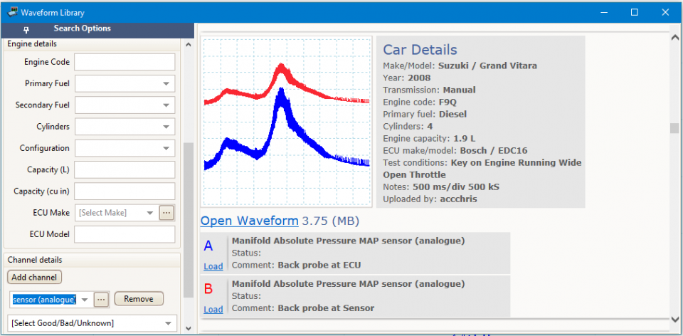
Waveform library
The Waveform Library is a global database of waveforms uploaded by PicoScope users.

Case studies
Real-life case studies show how the professionals use PicoScope to diagnose vehicle faults.

A to Z of PicoScope
Detailed description of various PicoScope software and hardware features.

Videos
Training resources and demonstrations on PicoScope and the Automotive Diagnostics Kit.

Newsletter
Archive of our monthly Automotive Newsletters.

Documentation
Download manuals, brochures, posters, and training materials.

Reviews and awards
Accolades for the preferred diagnostic tool for service centers and vehicle manufacturers.


Multimeter Probes

Back-pinning Probe Set

Flexible Back-pinning Probe

Large Dolphin/Gator Clips
*At Pico we are always looking to improve our products. The tools used in this guided test may have been superseded and the products above are our latest versions used to diagnose the fault documented in this case study.
The purpose of this test is to investigate the operation of an analog type Manifold Absolute Pressure (MAP) sensor on a turbo diesel engine during idle, free revving and overrun conditions.
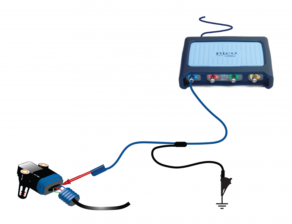
View connection guidance notes.
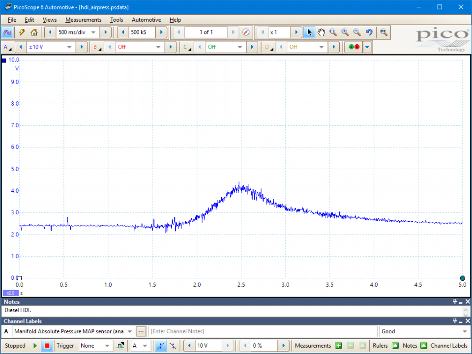
This known good waveform has the following characteristics:
Go to the drop-down menu bar at the lower left corner of the Waveform Library window and select Manifold Absolute Pressure MAP sensor (analogue).

MAP sensors respond to the air pressure within the intake manifold and allow the Engine Control Module (ECM) to estimate two important parameters:
The sensor can be mounted on the manifold housing or remotely, with pipework connecting the sensing element to the manifold volume.
The sensing element is usually a piezoelectric strain gauge having a voltage output proportional to the manifold air pressure. They require three electrical circuit connections:
MAP sensors measure absolute pressures. i.e. they are zero referenced against a perfect vacuum. The ECM will use known MAP sensor calibration values to convert the sensor signal voltage to an estimate of absolute pressure. At sea level, atmospheric pressure averages about 1013 mbar or 101.3 kPa. Therefore, when the ignition is on and the engine is off, the sensor output will be a positive, non-zero, voltage, which the ECM will interpret as a pressure around 1013 mbar or 101.3 kPa (dependent on the exact atmospheric conditions at the time).
On turbocharged engines, manufacturers use sensors capable of measuring pressure both above and below atmospheric pressures. Therefore, they can provide a measure of the boost (extra air mass) provided by the turbocharger.
Generally, MAP sensors fall into three pressure measurement categories, ranging from atmospheric, up to:
Modern diesel engine turbochargers can produce around 2.7 bar boost. In this scenario, having the wrong type of sensor in the engine will send false data to the ECM, which can cause erratic/poor performance and possible engine damage.
Symptoms of a faulty MAP sensor:
Possible failures that can cause erroneous MAP sensor signals are:
Selection of component-related Diagnostic Trouble Codes (DTCs):
P0105
P0106
P0107
P0108
P0109
P1101
P1106
P1107
View more
GT010-EN
Disclaimer
This help topic is subject to changes without notification. The information within is carefully checked and considered to be correct. This information is an example of our investigations and findings and is not a definitive procedure.
Pico Technology accepts no responsibility for inaccuracies. Each vehicle may be different and require unique test
settings.
We know that our PicoScope users are clever and creative and we’d love to receive your ideas for improvement on this test. Click the Add comment button to leave your feedback.


