PicoScope 7 Automotive
Available for Windows, Mac, and Linux, the next evolution of our diagnostic scope software is now available.
Automotive guided tests
Library of examples on how to perform tests when using PicoScope.

Training
Our collection of training videos, articles, guides and information on training courses.

Waveform library
The Waveform Library is a global database of waveforms uploaded by PicoScope users.

Case studies
Real-life case studies show how the professionals use PicoScope to diagnose vehicle faults.

A to Z of PicoScope
Detailed description of various PicoScope software and hardware features.

Videos
Training resources and demonstrations on PicoScope and the Automotive Diagnostics Kit.

Newsletter
Archive of our monthly Automotive Newsletters.

Documentation
Download manuals, brochures, posters, and training materials.

Reviews and awards
Accolades for the preferred diagnostic tool for service centers and vehicle manufacturers.


Multimeter Probes

Large Dolphin/Gator Clips

Back-pinning Probe Set

Premium Test Leads: Set of four leads 3 m (TA125 - TA128)
*At Pico we are always looking to improve our products. The tools used in this guided test may have been superseded and the products above are our latest versions used to diagnose the fault documented in this case study.
The purpose of this test is to check the rectification of the alternator output voltage, where the alternator output is not regulated by the Engine Control Module (ECM).
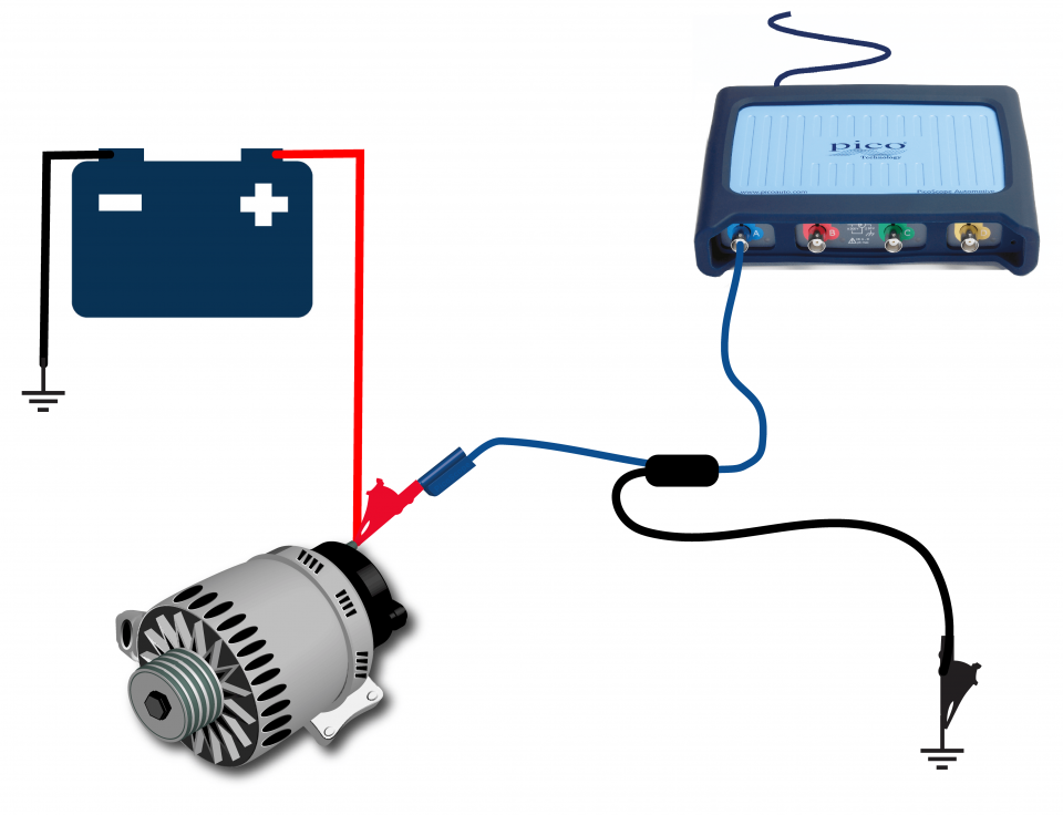
View connection guidance notes.
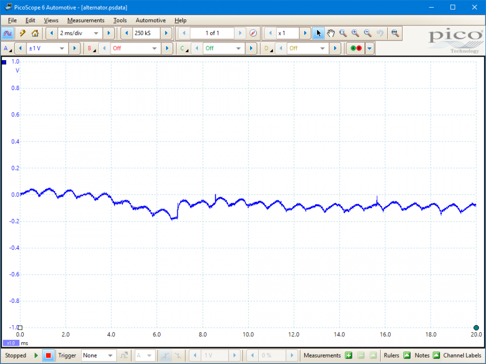
This known good waveform has the following characteristics:
Go to the drop-down menu bar at the lower left corner of the Waveform Library window and select Alternator AC ripple / Diode Test.

When the engine is running, an alternator generates electrical energy to supply the vehicle’s on-board electrical systems and replace the battery charge consumed during cranking.
The alternator converts mechanical rotation to electrical energy by causing a magnetic field to rotate within a fixed set of windings. The changing magnetic field induces AC voltages within the windings, which are rectified by an arrangement of diodes to give a DC output.
The maximum output is limited by a voltage regulator, which varies the alternator output relative to the system voltage; when the system voltage is low, the regulator increases the alternator output, and vice versa.
The rectification of the generated AC current creates a continuous series of voltage pulses, a ripple, within the alternator’s output. Periodically missing pulses or disruptions within the ripple indicate a problem with either the windings or the rectification diodes. Sharp spikes, usually downward, between the pulses indicate diode failure and the presence of unrectified AC voltage in the circuitry.
The alternator output will vary with engine speed and electrical load. However, a consistent ripple must be maintained throughout these variations.
Turning on electrical consumers and increasing the engine speed will increase the alternator load which can provoke faults that are not evident at low loads. If the peak to peak output voltages are above 500 mV, the offending voltage spikes may disrupt other electrical systems, in particular those systems dependent on an AC signal.
For an accurate and reliable signal always connect at the alternator B+ terminal: it is convenient to measure the ripple directly at the battery positive terminal; however, the battery can dampen the waveform such that problems can be missed.
Typical symptoms of faulty alternator would be:
Alternator, or related, faults that can cause the above symptoms are:
Selection of component related Diagnostic Trouble Codes (DTCs):
P0620
P0621
P0622
P0623
P0624
P0625
P0626
View more
GT002
Disclaimer
This help topic is subject to changes without notification. The information within is carefully checked and considered to be correct. This information is an example of our investigations and findings and is not a definitive procedure.
Pico Technology accepts no responsibility for inaccuracies. Each vehicle may be different and require unique test
settings.
We know that our PicoScope users are clever and creative and we’d love to receive your ideas for improvement on this test. Click the Add comment button to leave your feedback.


