PicoScope 7 Automotive
Available for Windows, Mac, and Linux, the next evolution of our diagnostic scope software is now available.
Automotive guided tests
Library of examples on how to perform tests when using PicoScope.

Training
Our collection of training videos, articles, guides and information on training courses.

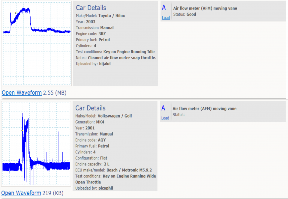
Waveform library
The Waveform Library is a global database of waveforms uploaded by PicoScope users.

Case studies
Real-life case studies show how the professionals use PicoScope to diagnose vehicle faults.

A to Z of PicoScope
Detailed description of various PicoScope software and hardware features.

Videos
Training resources and demonstrations on PicoScope and the Automotive Diagnostics Kit.

Newsletter
Archive of our monthly Automotive Newsletters.

Documentation
Download manuals, brochures, posters, and training materials.

Reviews and awards
Accolades for the preferred diagnostic tool for service centers and vehicle manufacturers.


Back-pinning Probe Set

PicoScope Battery Clip

Premium Test Lead: BNC to 4 mm, 3 m
*At Pico we are always looking to improve our products. The tools used in this guided test may have been superseded and the products above are our latest versions used to diagnose the fault documented in this case study.
The purpose of this test is to evaluate the voltage output from the internal track of the air flow meter during engine idle, Wide Open Throttle (WOT) and over-run conditions.
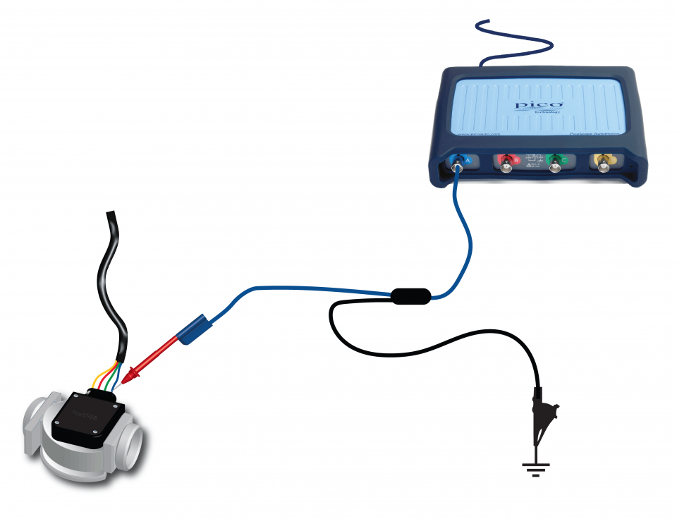
View connection guidance notes.
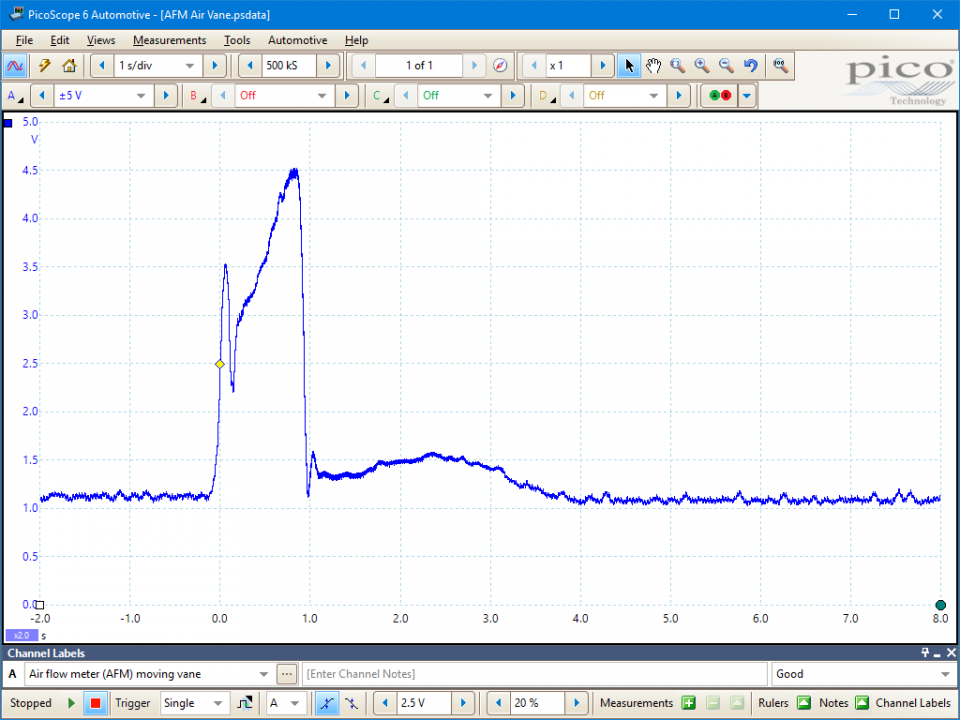
This known good waveform has the following characteristics:
Go to the drop-down menu bar at the lower left corner of the Waveform Library window and select Air flow meter (AFM) moving vane.

Vane-type air flow meters indicate the quantity of air flowing into an engine. They consist of a spring-loaded vane flap, which is deflected by the air flowing past it. The air vane is mechanically linked to an electrical contact, which slides across a carbon track as the vane moves. The effect is that of a variable resistor providing a varying voltage output relative to vane position. The Engine Control Module (ECM) uses the sensor output voltage to adjust the fuelling in proportion to the indicated air flow.
Vane-type air flow meters have a number of technical drawbacks.
For these reasons vehicle manufacturers have moved on to alternative methods of air flow measurement.
Depending on the vehicle application, Vane- type units were commonly found with any one of the following different types of electrical connector:
Four-terminal units can have-
Five-terminal units; as the four-terminal unit with the addition of-
Seven-terminal units; as the four-terminal unit with the addition of-
The fuel pump contacts make and break the circuit depending on the air flow through the meter. The circuit is made only when the incoming air has moved the flap approximately 5° from its rest, engine off position. This type of unit was fitted to certain Range Rover vehicles.
Vane-type air flow meters also have an internal compensation chamber that helps to stabilise the movement of the flap caused by induction pulses.
The CO content adjustment is via an internal air bypass or a potentiometer, depending on the version.
This type of air flow meter has been used on systems such as Bosch L, LE, LE3, Motronic and Ford EEC IV and several Japanese manufacturers.
Selection of component related Diagnostic Trouble Codes (DTCs):
P00BC
P00BD
P00BE
P00BF
P0100
P0101
P0102
P0103
P0104
P010A
P010B
P010C
P010D
P010E
View more
GT008-EN
Disclaimer
This help topic is subject to changes without notification. The information within is carefully checked and considered to be correct. This information is an example of our investigations and findings and is not a definitive procedure.
Pico Technology accepts no responsibility for inaccuracies. Each vehicle may be different and require unique test
settings.
We know that our PicoScope users are clever and creative and we’d love to receive your ideas for improvement on this test. Click the Add comment button to leave your feedback.


