PicoScope 7 Automotive
Available for Windows, Mac, and Linux, the next evolution of our diagnostic scope software is now available.
Automotive guided tests
Library of examples on how to perform tests when using PicoScope.

Training
Our collection of training videos, articles, guides and information on training courses.

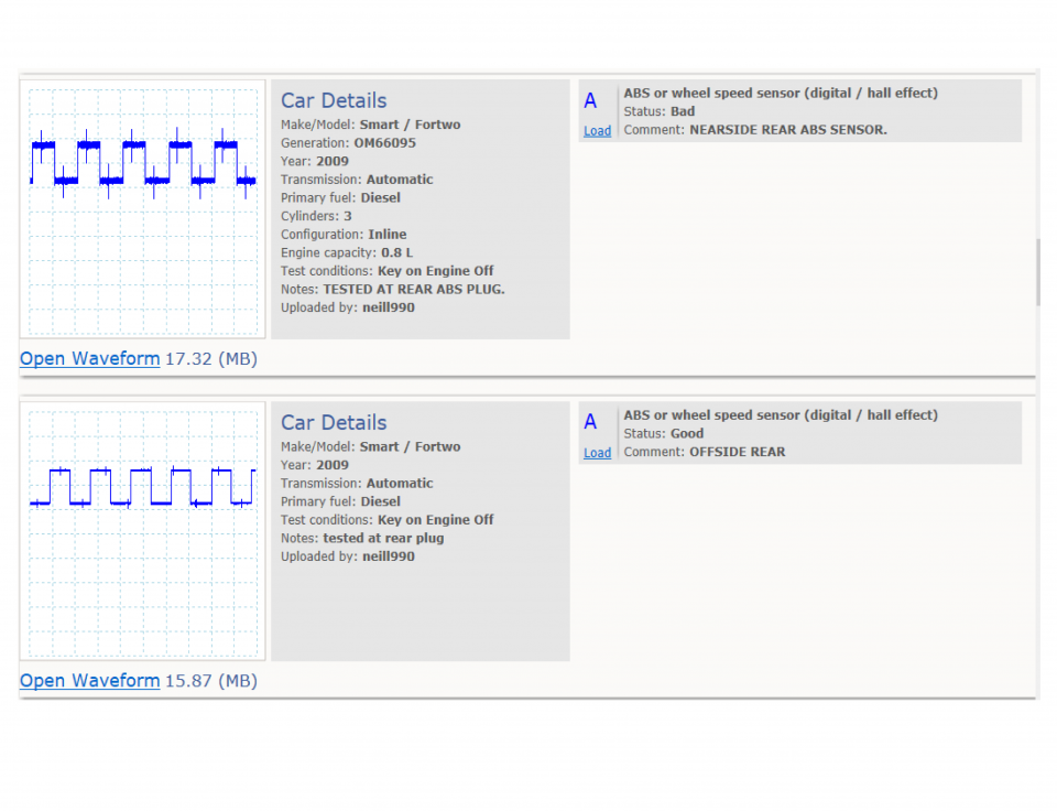
Waveform library
The Waveform Library is a global database of waveforms uploaded by PicoScope users.

Case studies
Real-life case studies show how the professionals use PicoScope to diagnose vehicle faults.

A to Z of PicoScope
Detailed description of various PicoScope software and hardware features.

Videos
Training resources and demonstrations on PicoScope and the Automotive Diagnostics Kit.

Newsletter
Archive of our monthly Automotive Newsletters.

Documentation
Download manuals, brochures, posters, and training materials.

Reviews and awards
Accolades for the preferred diagnostic tool for service centers and vehicle manufacturers.


Multimeter Probes

Back-pinning Probe Set

Flexible Back-pinning Probe

PicoScope Battery Clip
*At Pico we are always looking to improve our products. The tools used in this guided test may have been superseded and the products above are our latest versions used to diagnose the fault documented in this case study.
The purpose of this test is to evaluate the operation of an Antilock Braking System (ABS) Hall effect wheel speed sensor based upon its output voltage and frequency.

View connection guidance notes.
Access to individual wheel-speed sensors may be difficult.
All wheel-speed sensors connect to the ABS control module, which is usually located in the engine bay.
Note
PicoScope sets Channel A and Channel B: connect both channels to have comparative waveforms.
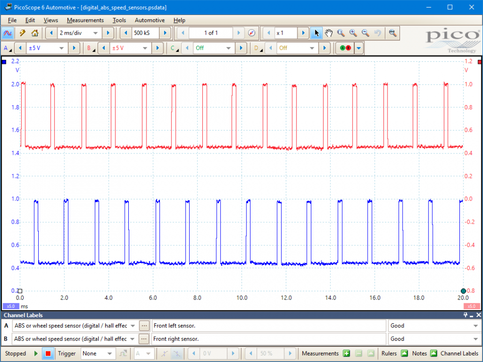
These known good waveforms have the following characteristics:
Go to the drop-down menu bar at the lower left corner of the Waveform Library window and select ABS or wheel speed sensor (digital / hall effect).

Wheel speed sensors provide wheel and road speed feedback to ABS and derivative active vehicle safety systems (i.e. stability and traction control etc.).
These systems are designed to provide corrective action (e.g. wheel braking or engine torque limitation) when the vehicle chassis or wheel speeds have exceeded their normal operational tolerances, for example, during conditions of wheel slip, oversteer or understeer etc. Wheel speed sensors are critical to the operation of these systems and, therefore, the safe handling of a vehicle.
A Hall effect sensor is a semiconductor device that creates a voltage output in proportion to an applied magnetic field. A Hall effect wheel speed sensor uses this technology to produce a square wave output in response to the magnetic field disturbances caused by a rotating pulse wheel mounted around a hub or driveshaft.
Hall effect wheel speed sensors require power to operate; hence they are referred to as active sensors. These sensors always have a positive supply voltage, usually 5 V, on one terminal; however, they may have one of two terminal configurations:
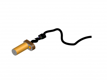
It is not easily possible to distinguish two wire passive (inductive) and active (Hall or magnetoresistive) wheel speed sensors by their external appearance. Diagnostically, this is inconvenient as active wheel speed sensors must never be subjected to resistance tests: this can damage these units, with the only remedy being the acquisition of a new replacement.
Therefore, you must always either consult manufacturer’s data to identify the fitted type prior to diagnostic testing or carry out a speculative PicoScope check to identify the sensor from its output voltage characteristics.
You can check for a positive supply voltage at one of the sensor connector terminals to determine if you have an active sensor type. However, if the supply voltage is missing due to a fault and you then assume the sensor must be passive and perform a resistance check, you can damage a perfectly good active sensor. This will give you two faults.
An ABS control module expects similar (within a given tolerance) square wave frequencies from all the vehicle’s wheel speed sensors and uses any differences to calculate the timing and scale of its interventions.
If one, or more, wheel speed signals continuously fall outside of normal parameters the control module may turn the ABS function off (along with associated traction and stability systems). A driver warning light will be illuminated but, as with any electrical fault on ABS, normal hydraulic braking is maintained.
Wheel speed sensors and their pulse rings are exposed to the atmosphere and have to operate under conditions of constant vibration and movement. As such, common faults are:
Wheel speed sensor circuits and connectors are also prone to the atmosphere and possible electrical failures, such as open or short circuits or high circuit resistances.
Active wheel speed sensors are susceptible to damage from incorrect testing methods; in particular, the application of resistance testing.
Symptoms of ABS sensor related faults
Selection of component related Diagnostic Trouble Codes (DTCs):
C0000
C0035
C0036
C0040
C0041
C0045
C0046
C0050
C0051
C0221
C0222
C0223
C0225
C0226
C0227
C0229
C0235
C0236
C0237
C0238
C0245
C0300
C0305
C0226
C0227
C0229
C0235
C0236
C0237
C0238
C0245
C0300
C0305
View more
GT072
Disclaimer
This help topic is subject to changes without notification. The information within is carefully checked and considered to be correct. This information is an example of our investigations and findings and is not a definitive procedure.
Pico Technology accepts no responsibility for inaccuracies. Each vehicle may be different and require unique test
settings.
We know that our PicoScope users are clever and creative and we’d love to receive your ideas for improvement on this test. Click the Add comment button to leave your feedback.


