PicoScope 7 Automotive
Available for Windows, Mac, and Linux, the next evolution of our diagnostic scope software is now available.
Automotive guided tests
Library of examples on how to perform tests when using PicoScope.

Training
Our collection of training videos, articles, guides and information on training courses.

Waveform library
The Waveform Library is a global database of waveforms uploaded by PicoScope users.

Case studies
Real-life case studies show how the professionals use PicoScope to diagnose vehicle faults.

A to Z of PicoScope
Detailed description of various PicoScope software and hardware features.

Videos
Training resources and demonstrations on PicoScope and the Automotive Diagnostics Kit.

Newsletter
Archive of our monthly Automotive Newsletters.

Documentation
Download manuals, brochures, posters, and training materials.

Reviews and awards
Accolades for the preferred diagnostic tool for service centers and vehicle manufacturers.

| Vehicle details: | Proton Impian |
| Symptom: | P0340 |
A Proton Impian was suffering from intermittent non-starting, and the vehicle randomly cut out. This caused the engine warning light to illuminate.
The first stage of the investigation was to use a diagnostic tool and obtain any ‘DTC’ (Diagnostic Trouble Codes) information and relevant data from the ECU. However, when this was tried, there was no communication with the scan tool. At this point it was unknown whether the scan tool or the ECU of the vehicle was at fault.
The CAN test box was plugged into the vehicle’s diagnostic port, and the CAN High and CAN Low pins illuminated, indicating power from the ECU to the diagnostic port. At this stage the scan tool was plugged into the CAN test box. Still there was no communication, no K–line activity. This implies a fault on the scan tool lead, or communication key. Further investigation revealed the scan tool lead had a dirty connection on the communication key.
Once the connection of the communication key was cleaned, it was possible to extract the DTC codes from the vehicle:
P0340 — CAMSHAFT POSITION SENSOR CIRCUIT ‘A’ BANK 1 OR SINGLE CIRCUIT
The DTC was cleared, and all tools disconnected from the vehicle. A road test was performed. On return to the garage and with the engine still running the cam sensor was scoped, as you can see in the waveform below.
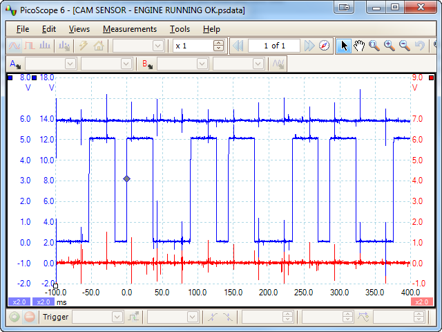
The engine was then switched off, and would not re–start. The CAN test box and scan tool were connected to the vehicle via the diagnostic port, and the same DTC was extracted as before. The Camshaft sensor was then scoped, and the below waveform recorded.

This revealed the Camshaft sensor was at fault.
The faulty Camshaft sensor was replaced. The DTC was cleared, the car was started, and the new cam sensor was scoped.
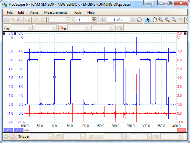
A road test was then completed. On return to the garage the ECU was checked for DTCs and none were found.
Dave
October 31 2011
The diagnosis is a failure of the transistor to pull the 5 vdc signal to ground. The hall switch fires the ignitor on the rise or positive slope, however if not pulled to zero it does not trigger.
Aaron
October 31 2011
Interesting, I can see the wave and did not realise that the voltage had to drop so much ie down to 2v.
Great that you were lucky enough to see it in a good state.
Good example of why a known good archive on say a wiki type site would be fantastic
Aaron
Robski
October 31 2011
Hi Anonymous, nice to capture the fault in the act.
I have one question,why do you have two blue traces as if there are two channel A’s,are you running a math channel or similar ?
Nice job,
Cheers
Rob.
phil j
October 31 2011
good presentation, my only advise would be to mirror what two other comments mentioned in that you should have mentioned what the other two channels were measuring. obvious to some maybe not to others.
phil j
October 31 2011
Aaron, i think you are mixing up the two channels measuring nominal battery voltage and the signal from the cam sensor which is switching to zero volts up to six volts on a digital square wave. unless i have got that wrong myself in thinking that?
Dave Hill
October 30 2011
That is a nice demonstration, which shows how to observe a sensor failure in real time.
I have not seen a failure quite like that before, so thanks for bringing it to our attention.
I take it that the other two channels are capturing the power & ground?
One other point that might lead to some confusion is the comment about the “communication key”. I take it that this refers to the “personality keys” that a certain scantool provider uses, to configure their tool to the variety of vehicle protocols?
Nice work by the way, whoever you are. (I didn’t see the authors name)
Regards
Dave
David Paterson
October 30 2011
I liked the first and the last parts of your efforts. Firstly, you made good use of the CAN box to elimate there being no supply, and it clearly helped you find out why the Scan tool wasn’t communicating.
What scope software were you using? Your traces show differences, but it would have been helpful to show more detail of your findings - ie presumably a Hall Effect sensor, and what you were measuring with each channel - not obvious to every user!
Finally, good to see that having changed the component you did both erase the fault code and confirm that it didn’t come back. Hope this isn’t taken the wrong way, as in general it was appreciated, and it is a lot easy to be critical than to do the job you did. Keep them coming!
colin hogarth
October 30 2011
good competent repair.


