PicoScope 7 Automotive
Available for Windows, Mac, and Linux, the next evolution of our diagnostic scope software is now available.
Automotive guided tests
Library of examples on how to perform tests when using PicoScope.

Training
Our collection of training videos, articles, guides and information on training courses.

Waveform library
The Waveform Library is a global database of waveforms uploaded by PicoScope users.

Case studies
Real-life case studies show how the professionals use PicoScope to diagnose vehicle faults.

A to Z of PicoScope
Detailed description of various PicoScope software and hardware features.

Videos
Training resources and demonstrations on PicoScope and the Automotive Diagnostics Kit.

Newsletter
Archive of our monthly Automotive Newsletters.

Documentation
Download manuals, brochures, posters, and training materials.

Reviews and awards
Accolades for the preferred diagnostic tool for service centers and vehicle manufacturers.

| Vehicle details: | Jaguar X Type |
| Engine code: | QJB |
| Year: | 2006 |
| Symptom: | P0405, P132A, Power loss |
| Author: | Steve Smith |

20 A / 60 A DC (low amps) current clamp
*At Pico we are always looking to improve our products. The tool used in this case study may have been superseded and the product above is our latest version used to diagnose the fault documented in this case study.
Engine warning light became illuminated, accompanied with severe lack of power under acceleration after changing gear or when pulling away from rest (evident for approximately 3 weeks).
The customer’s description of the problem was accurate, with an obvious and abrupt loss of power under acceleration during our road test. It would appear the vehicle reverted to limp mode (where the ECU restricts performance and or gearing when a fault is detected) as no power was restored until the ignition was cycled (off to on). Upon restarting the engine, all power was restored and the engine warning light extinguished until attempting to accelerate where the above symptom would return.
The customer interview revealed information regarding the vehicle. Full service history was apparent and no aftermarket accessories had been installed. A recent EGR (exhaust gas recirculation) valve replacement had also taken place. The customer complaint was verified and the vehicle’s identification and specification were confirmed.
A basic inspection highlighted the turbocharger intake pipe to be split. Visible connections were secure, there was evidence of the new EGR valve installation and the wiring harness to be routed correctly (the split turbocharger hose was rectified immediately with no effect on the symptom).
A vehicle scan confirmed engine fault codes indicating circuit errors with both the EGR valve and Turbocharger boost control position sensor.

Available VM (vehicle manufacturer) service data confirmed no outstanding issues relevant to turbocharger boost control other than numerous forum posts surrounding both EGR valve and turbo boost control actuator failure. While it is always tempting to rely heavily on the internet for direction or a cure, we must obtain evidence in order to qualify the replacement of any component. Once we have the evidence we can provide conclusive before and after repair data for our customer, or warranty if applicable.
Armed with the knowledge that an EGR valve had already been installed, the fault codes were saved and erased before monitoring live data from the PCM, with regards to turbocharger boost control and engine speed. Here the engine was free revved while stationary to monitor the operation of the boost control actuator control rod (linking the actuator to the turbo vanes).
The image below indicates the moment turbo boost control is suspended by the PCM before illuminating the engine warning light (only fault code P132A returned). At this point in time the vehicle is now in limp mode where the turbo vanes are returned to the rest position with no further activity from the actuator control rod until the ignition is cycled as mentioned above.

The manufacturer’s description and operation was referenced for in-depth knowledge of component functions (this knowledge is imperative when diagnosing any system and highlights the need for continual research and training). EGR fault was ruled out at this stage based on the instant appearance of boost control fault code P132A without EGR code P0405.
Possible causes based on symptom and non-intrusive evaluations made above:
The action plan is based on initial evaluation, experience, and accessibility; hence, the boost control position sensor circuit had to be measured for integrity using PicoScope.
The boost control actuator utilises a 5-pin connector using four wires, where two wires supply power and ground (green/orange and black/red) to the internal actuator motor and the remaining two wires are linked to the CAN network (blue/red and grey/red).
The revelation here is that the Boost Control Actuator position is relayed to the PCM via the CAN network and not as I assumed based on the fault code “Turbo boost Control Position Sensor circuit”.
This would explain how the PCM was able to report a “Turbo Boost Control Position Sensor” circuit error while also provide information such as variable geometry turbo duty cycle (via scan tool data) from just two wires! I have no doubt far more data will be exchanged via CAN between the Boost Control Actuator and the PCM. Here then our diagnosis takes a different approach.
Keeping it simple to start with (never over-complicate when unnecessary) the power and ground to the actuator motor were inspected using PicoScope where a number of concerns became apparent within the images below:

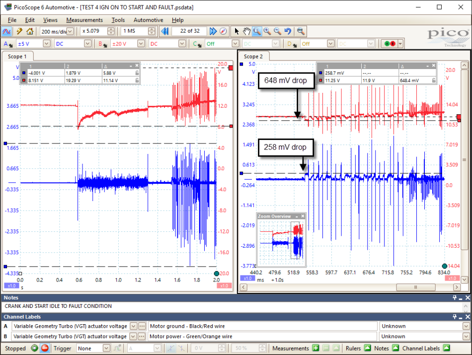
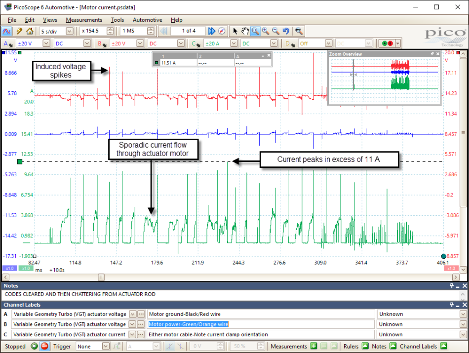
The amount of noise present on the actuator motor circuit and the voltage drop seen during operation gave reason for concern. Either the circuit integrity or the component (actuator motor) were suspect as we appeared to have captured induced voltage spikes in excessive of 11 V on the power side and 5 V on the ground during actuator motor operation. Such events can be attributed to high frequency current switching (think of an ignition coil) where current flow is interrupted resulting in the momentary collapse of a magnetic field. The use of a current clamp here will reveal the nature of current flow through the actuator motor in relation to rotation (work done). The following PicoScope capture highlights the sporadic current flow through the actuator motor during operation with peak current spikes reaching 11 A at high frequency. These are the exact conditions required to produce the voltage drop and noise (induced voltage) seen during our initial capture.
It would appear at this stage we have sufficient evidence to warrant further investigation of the Turbo Boost Control Actuator but what about the stability of the CAN circuit from the actuator during operation (before limp mode), this cannot be ignored!
The CAN circuit must be inspected using PicoScope to ensure accurate formation of the CAN signal accompanied with confirmation of communication (NB. No CAN codes were discovered during the initial vehicle scan). The physical layer is the actual differential voltage signal (CAN Hi minus CAN Lo [0 – 2 V]) used by the CAN network to transport serial data
The scope trace below confirms the CAN physical layer to be intact with a stable baseline voltage at 2.5 V and respectable CAN Hi/Lo voltages. With the addition of a Math Channel (B - A) we can also reveal the differential voltage utilised by the nodes present on the network. The use of a Math Channel (B – A) will assist with an in‑depth view of the amount of noise present on the CAN network as subtracting CAN Hi from CAN Lo should remove any noise present where the noise is equal and opposite in both circuits (CAN Hi and CAN Lo).
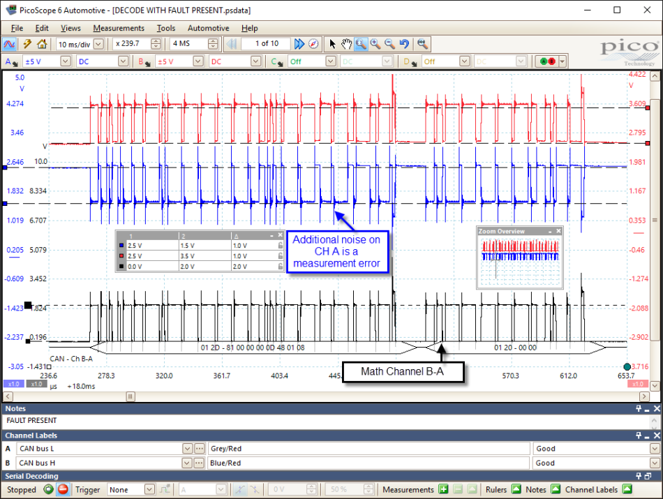
From the waveform above we can see the Math Channel does incorporate noise due to additional spikes present on channel A but not channel B. This is not a fault with the vehicle but more a measurement error on my behalf as Math Channel B – A is usually a near perfect 0 – 2 V.
To create a Math Channel click on “Tools > Math Channels > Create > Next”. Enter the following equation into the formula box “B – A”. Follow the Math Channel Wizard through choosing a name, colour and scale for your creation and finally tick the box adjacent to your “Math Channel B – A” in the Math Channel Library (this will appear once you completed the Wizard).
Having confirmed the physical layer to be in good condition how could we confirm communication to be present and more importantly, no errors within the communicated data?
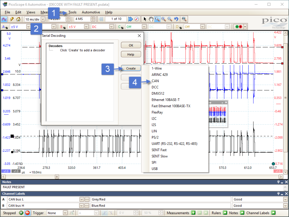
Using the serial decoding feature of PicoScope we can decode the CAN signal on any of the waveforms (including the Math Channel). The Math Channel would be my preferred choice as this would normally incorporate minimal noise and is the exact signal form used by the nodes present on the CAN network. To decode the CAN data contained within the created Math Channel, click on “Tools > Serial Decoding > Create > CAN”. The CAN configuration box will now appear asking for details on which channel you wish to decode, such as: voltage thresholds, noise level (hysteresis) and network speed (Baud Rate). Use the settings in the image to the right to obtain sufficient serial decode data.


With the displayed decoded data we can confirm no errors exist in each of the CAN frames captured.
Whilst we cannot convert the decoded data into plausible data (manufacturer proprietary information) we can confirm communication to be taking place, the construction of the physical layer to be correct (good waveform structure) and no errors to exist within the decoded data (errors within CAN frames will be highlighted in red).
Accompany these facts with no CAN communication error codes (“U” codes) we can conclude the Boost Control Actuator to be functioning correctly from a CAN network point of view. Even to the point of reporting the correct live serial data to the scan tool and informing the PCM of the Boost Control Position Sensor error.
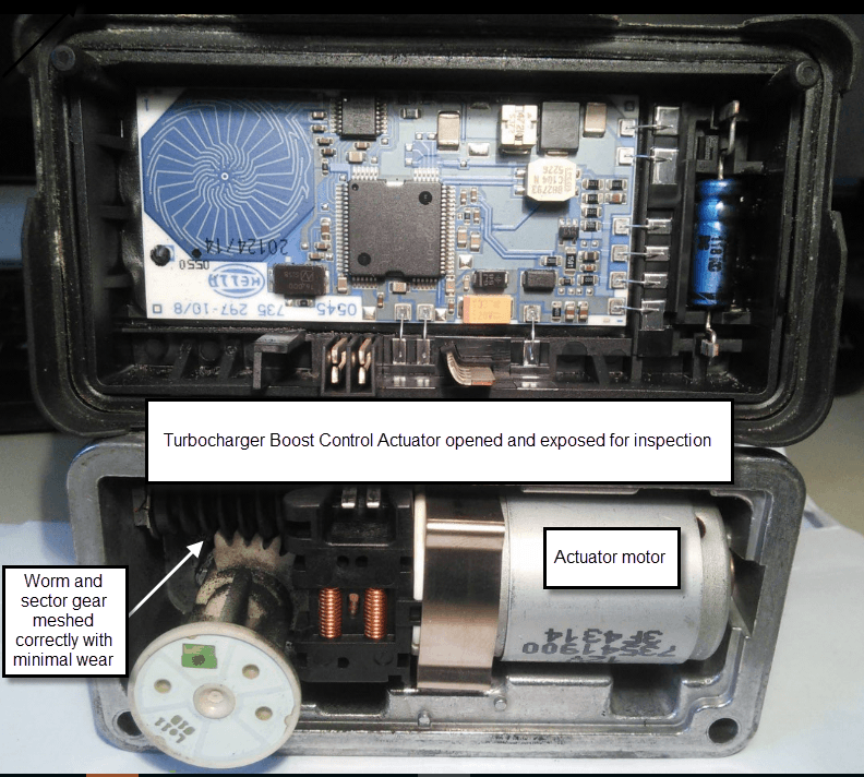
Returning now to the internal actuator motor fault, the images below tell their own story as the Turbo Charger Boost Control Actuator was removed and dismantled for closer inspection of the motor commutator and brushes.

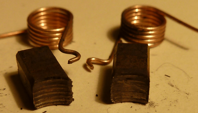
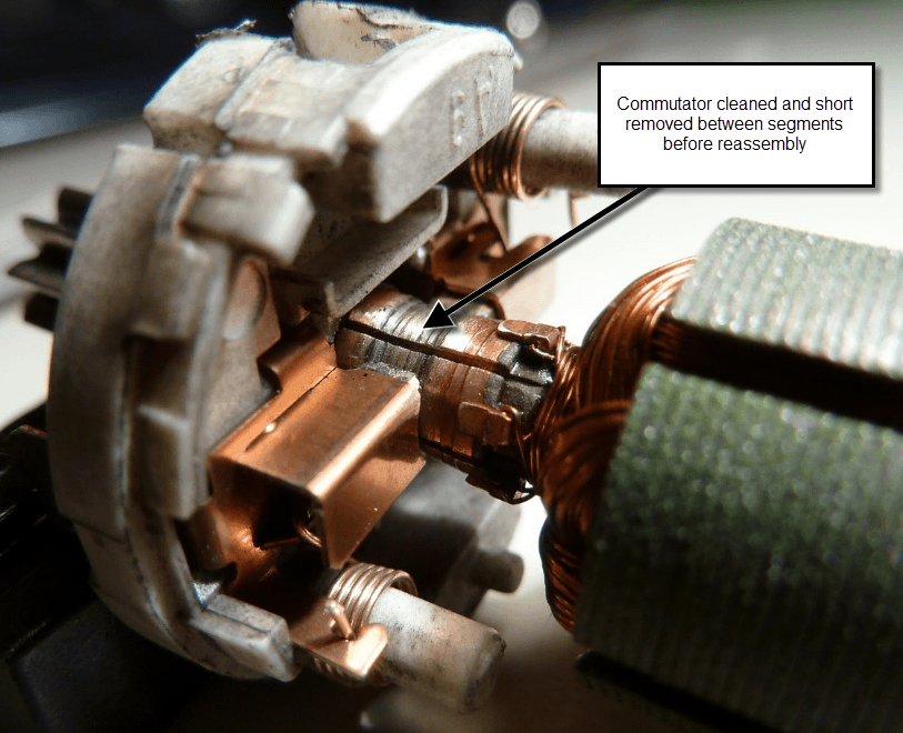
Looking at the condition of the commutator and brush wear characteristics, it is no surprise why the current flow momentarily exceeded 11 A accompanied with the high frequency current spikes that we can now attribute to arcing as the motor rotates. After removing the contamination between the armature segments and cleaning the contact surfaces of the brushes the Turbo Boost Control Actuator was reassembled and refitted to the vehicle for research purpose only.
The waveforms below indicates the improvement to the amount of induced voltage detected in both the actuator motor power and ground circuits along with a reduction in peak current. Note the nature of the current ramps in relation to motor operation.
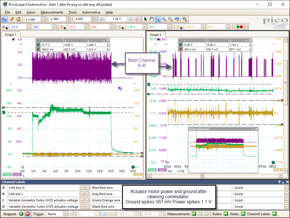
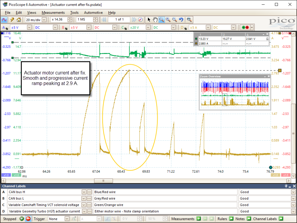
Current ramps are now smooth, progressive (minus the spikes) with an instantaneous drop to zero when the actuator motor is required to halt.
The above vehicle most certainly requires a Turbo Boost Control Actuator to ensure reliability for future service. Refurbishment of the Turbo Boost Control Actuator has rectified the customers concern at present, with power restored under acceleration and no return of a fault code.
Below is a video of the Turbo Boost Control Actuator after fix during free revving and ignition off:
I think it is safe to conclude that Pico current clamps remain essential accessories to any diagnostic tool set. When included with PicoScope hardware and software the case study above demonstrates the further potential of what is often overlooked as a tool of choice during diagnosis.
The current clamp chosen during the above case study (20/60 Low Amps clamp TA018) presented undeniable evidence that the actuator motor had failed due to the sporadic nature of current flow and peak current draw when attempting to rotate.
By its nature, the current clamp has to be the most non-intrusive diagnostic tool that is capable of capturing events not seen when measuring voltage, while secretly confirming “voltage/ground” and component to be functioning correctly based on Ohms Law.
You could argue if current flow is correct, then voltage/ground and component are functioning normally, so saving you two precious scope channels for other measurements!
Further examples of current clamp applications revealing anomalies
https://www.picoauto.com/library/case-studies/1961-jaguar-e-type-3-8-unstable-idle-speed
https://www.picoauto.com/library/case-studies/2007-toyota-hilux-2-5-tdi-p0340-p0335
https://www.picoauto.com/library/case-studies/juddering-at-low-speed
dave baxter
July 28 2016
I’m just amazed that actuator used a brushed motor, not brushless or stepper for that function. No doubt a cost reduction measure, and sod the customer or own company’s product reputation.
stephen Kasapis
July 28 2016
This is great work showing everyone how important using a Scope can be


