PicoScope 7 Automotive
Available for Windows, Mac, and Linux, the next evolution of our diagnostic scope software is now available.
Automotive guided tests
Library of examples on how to perform tests when using PicoScope.

Training
Our collection of training videos, articles, guides and information on training courses.

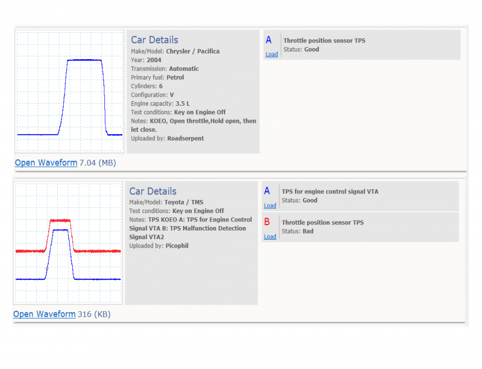
Waveform library
The Waveform Library is a global database of waveforms uploaded by PicoScope users.

Case studies
Real-life case studies show how the professionals use PicoScope to diagnose vehicle faults.

A to Z of PicoScope
Detailed description of various PicoScope software and hardware features.

Videos
Training resources and demonstrations on PicoScope and the Automotive Diagnostics Kit.

Newsletter
Archive of our monthly Automotive Newsletters.

Documentation
Download manuals, brochures, posters, and training materials.

Reviews and awards
Accolades for the preferred diagnostic tool for service centers and vehicle manufacturers.


Multimeter Probes

Back-pinning Probe Set

Flexible Back-pinning Probe

PicoScope Battery Clip
*At Pico we are always looking to improve our products. The tools used in this guided test may have been superseded and the products above are our latest versions used to diagnose the fault documented in this case study.
The purpose of this test is to examine the operation of a Throttle Position Sensor (TPS) potentiometer based on output quality and response time in relation to throttle position.
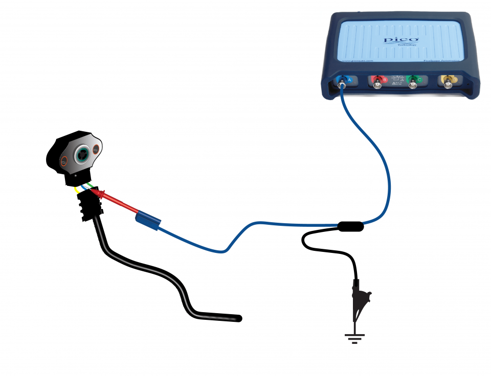
View connection guidance notes.
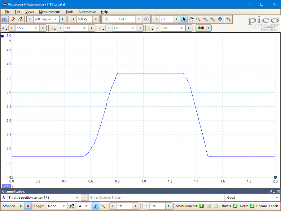
This known good waveform has the following characteristics:
Go to the drop-down menu bar at the lower left corner of the Waveform Library window and select Throttle position sensor TPS.

A throttle position sensor signals the position of the throttle valve to the Engine Control Module (ECM).
Throttle potentiometers are generally carbon track type units mounted directly onto the throttle butterfly spindle. They are a three-wire device with a reference 5 V supply, output signal and earth terminals.
Some manufacturers combine the potentiometer with the throttle actuator motor. Whether combined or separate components, their function remain the same.
As the throttle position is critical to engine control, the normal operating output range of the TPS is within some margin of the earth and reference 5 V supply voltages. For example, from around 0.5 V to around 4.5 V. This provides a means for the ECM to check the integrity of the sensor and circuits: a voltage below or above this expected output range will indicate an open circuit, a short to earth, or a short to the reference 5 V supply. Either of these outcomes will cause the ECM to register a sensor fault.
Faulty Throttle Potentiometer – Symptoms
Faulty Throttle Potentiometer – Causes
Selection of component related Diagnostic Trouble Codes (DTCs):
P0120
P0121
P0122
P0123
P0124
P0220
P0221
P0222
P0223
P0224
P0225
P0226
P0227
P0228
P0229
P0510
View more
GT029
Disclaimer
This help topic is subject to changes without notification. The information within is carefully checked and considered to be correct. This information is an example of our investigations and findings and is not a definitive procedure.
Pico Technology accepts no responsibility for inaccuracies. Each vehicle may be different and require unique test
settings.
We know that our PicoScope users are clever and creative and we’d love to receive your ideas for improvement on this test. Click the Add comment button to leave your feedback.


