PicoScope 7 Automotive
Available for Windows, Mac, and Linux, the next evolution of our diagnostic scope software is now available.
Automotive guided tests
Library of examples on how to perform tests when using PicoScope.

Training
Our collection of training videos, articles, guides and information on training courses.

Waveform library
The Waveform Library is a global database of waveforms uploaded by PicoScope users.

Case studies
Real-life case studies show how the professionals use PicoScope to diagnose vehicle faults.

A to Z of PicoScope
Detailed description of various PicoScope software and hardware features.

Videos
Training resources and demonstrations on PicoScope and the Automotive Diagnostics Kit.

Newsletter
Archive of our monthly Automotive Newsletters.

Documentation
Download manuals, brochures, posters, and training materials.

Reviews and awards
Accolades for the preferred diagnostic tool for service centers and vehicle manufacturers.


Multimeter Probes

PicoScope Battery Clip
*At Pico we are always looking to improve our products. The tools used in this guided test may have been superseded and the products above are our latest versions used to diagnose the fault documented in this case study.
The purpose of this test is to evaluate the operation of a Single Point Injection (SPI) injector based on the switching voltage, pulse width, and formation during engine run conditions.
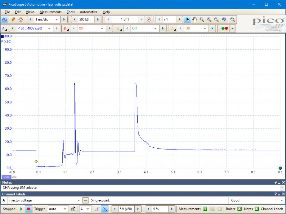
Note: This help file refers to a 20:1 attenuator. If you are using a 10:1 attenuator please adjust the Probe settings for the relevant channel. These settings can be found under the Channel Options button, then: Probe > 10:1 Attenuator.
WARNING
This test involves measuring a potentially hazardous voltage.
Please ensure you follow manufacturers' safety instructions and working practices and ensure the rated voltage for all accessories you are using meets or exceeds the expected voltage.
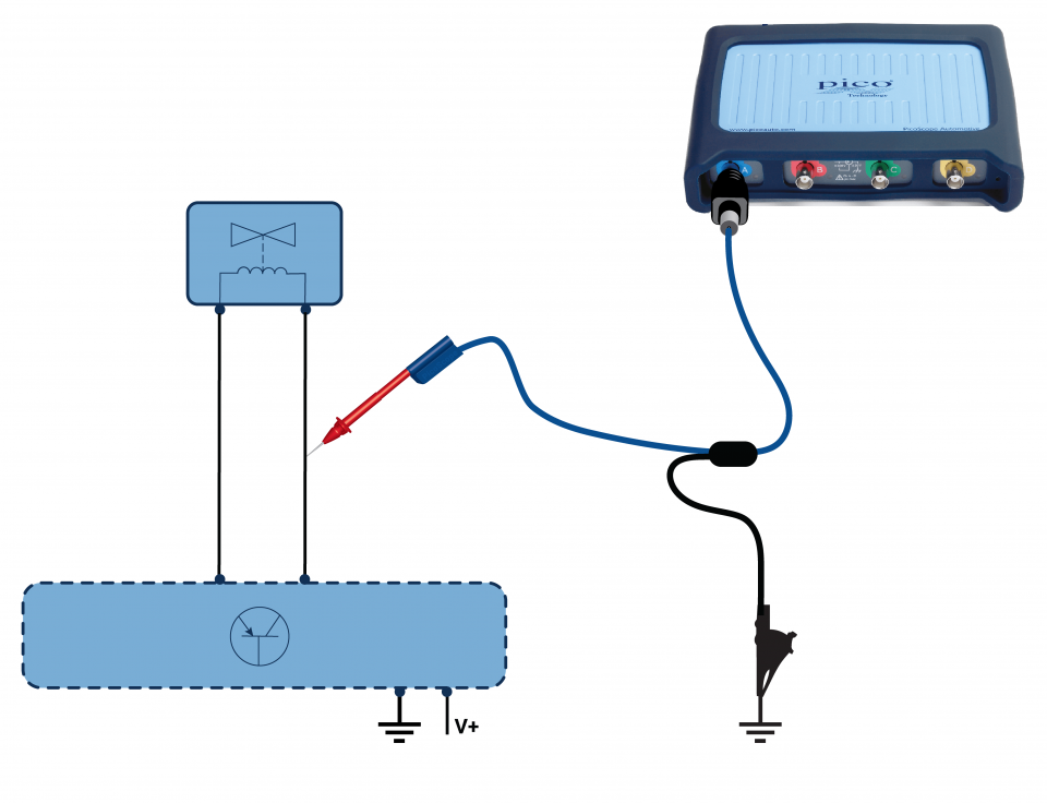
View connection guidance notes.
Single Point Injector (SPI) is also sometimes referred to as Throttle Body Injection (TBI).
A single injector is used (on larger engines two injectors can be used) in what may have the outward appearance of a carburettor housing.
The resultant waveform from the SPI system will show an initial injection period followed by multi-pulsing of the injector in the remainder of the trace. This section of the waveform is called the supplementary duration and is the only part of the injection trace to expand.
The reason that a single point injector is used rather than a multi-point configuration is sometimes hard to justify, and can only be due to a consideration towards costing and ease of application. A single injector is used (on larger engines two injectors can be used) in what may appear to be a carburettor housing.
It has a very low operating pressure (usually around 1 bar) and the atomising of the fuel can only be described as minimal, relying on the air movement within the inlet manifold to break the fuel down into smaller particles, ready for combustion.
Due to its design, the main advantage over a carburettor is that a lambda sensor can be employed ensuring that closed-loop control is maintained. Multi-point will undoubtedly ensure that the vehicle's engine has a higher power output with fewer exhaust emissions.
Due to the design of the system, a conventional air flow meter cannot be used and a map sensor is often employed.
GT037
Disclaimer
This help topic is subject to changes without notification. The information within is carefully checked and considered to be correct. This information is an example of our investigations and findings and is not a definitive procedure.
Pico Technology accepts no responsibility for inaccuracies. Each vehicle may be different and require unique test
settings.
We know that our PicoScope users are clever and creative and we’d love to receive your ideas for improvement on this test. Click the Add comment button to leave your feedback.


