PicoScope 7 Automotive
Available for Windows, Mac, and Linux, the next evolution of our diagnostic scope software is now available.
Automotive guided tests
Library of examples on how to perform tests when using PicoScope.

Training
Our collection of training videos, articles, guides and information on training courses.

Waveform library
The Waveform Library is a global database of waveforms uploaded by PicoScope users.

Case studies
Real-life case studies show how the professionals use PicoScope to diagnose vehicle faults.

A to Z of PicoScope
Detailed description of various PicoScope software and hardware features.

Videos
Training resources and demonstrations on PicoScope and the Automotive Diagnostics Kit.

Newsletter
Archive of our monthly Automotive Newsletters.

Documentation
Download manuals, brochures, posters, and training materials.

Reviews and awards
Accolades for the preferred diagnostic tool for service centers and vehicle manufacturers.


Secondary ignition pickup (capacitive with BNC)
*At Pico we are always looking to improve our products. The tool used in this guided test may have been superseded and the product above is our latest version used to diagnose the fault documented in this case study.
The purpose of this test is to evaluate the peak firing voltage of the ignition coil via a 30 kV test adapter under engine run conditions.
WARNING
Uninsulated HT pickups are designed to clip around double-insulated HT leads only – they are not designed for direct connection to a hazardous live voltage.
To prevent injury or death, when connecting or disconnecting an HT pickup:
Note: you will need a 30 kV ignition test adapter, available from your test equipment supplier.
Plug a high tension (HT) pick-up lead into Channel A on the PicoScope, clip the lead's fly lead on a suitable earth and clip the HT clip on to one of the engine's plug leads. Disconnect this plug lead (at the spark plug end) and insert the 30 kV test adapter as illustrated in Figure 1.
Using the secondary negative fired example waveform, first identify the two negative fired spark plugs. It will only be necessary to check the negative fired plugs on this system as a fault within one side of the coil pack will show up regardless of the polarity.
Plug a high tension (HT) pick-up lead into Channel A on the PicoScope, clip the lead's fly lead on a suitable earth and clip the HT clip on to one of the engine's negative fired plug leads. Disconnect this plug lead (at the spark plug end) and insert the 30 kV test adapter as illustrated in Figure 1.
Remove the coil pack and fit an extension adapter on to the spark plug. Attach the 30 kV test adapter, as illustrated in Figure 1, between the extension and the coil.
Plug a high tension (HT) pick-up lead into Channel A on the PicoScope, clip the lead's fly lead on a suitable earth and clip the HT clip on to the 30 kV test adapter.
The test procedure is the same for all of the above ignition systems. With the engine running and the oscilloscope displaying live readings, very carefully remove the connection to the spark plug (or extension adapter). This is done using suitably insulated pliers such as those shown in Figure 2. When the connection to the spark plug is removed, a spark should be seen inside the 30 kV tester. This gap is preset and at least 30 kV should be displayed on the oscilloscope if the coil in good enough condition. The pre-set waveform has the maximum voltage measurement displayed at the bottom of the screen.
Figure 3 shows the connections made on a negative-fired spark plug on a DIS system. Figure 4 shows the connection to the spark plug being removed.
Extreme care should be taken during this test as modern HT circuits can produce in excess of 60 kV. This voltage will damage the ignition system, and even the Electronic Control Module (ECM), if the test is not conducted properly.
When attaching or removing secondary ignition pickups from damaged HT leads, there is a danger of electric shock. To avoid this risk, attach and remove the secondary ignition pickup with the ignition turned off.
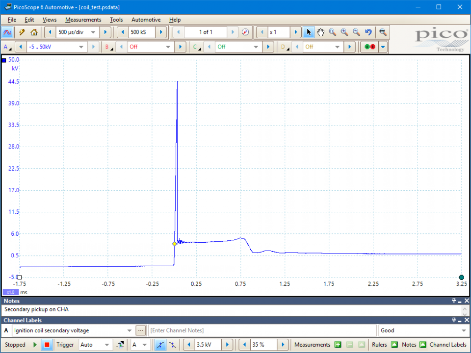
When testing the coil's maximum output with the HT lead removed, the kV spike on the oscilloscope will be higher than normal. The voltage to which it rises under these particular conditions, with the spark jumping the predetermined gap within the spark tester, is not the maximum possible voltage from the coil. The voltage recorded is merely the voltage required to jump the tester's air gap. With this in mind, the maximum voltage should be taken from the 'Ch A: Maximum (kV)' reading at the bottom of the screen. The maximum voltage recorded in this instance is 29.55 kV. If the operator were to completely open the HT circuit without the aid of a spark gap, the recorded voltage would be considerably higher but would risk causing damage to the primary switching circuits within the amplifier or ECM. This practice is therefore not advised.
A typical coil such as the DIS system fitted to this Ford Zetec engine produces upwards of 60 kV. A reduced output that will still jump the air gap can be recognised by the reduction in spark duration.
Further information on secondary waveforms can be found on the 'Secondary - distributor system king or plug lead' pages, selected from the main menu.
Inside the coil's primary winding is the secondary winding. This winding is coiled around a multi-laminated iron core and has about 20,000 to 30,000 turns. One end is connected to the primary terminal and the other to the coil tower.
The High Tension (HT) voltage is produced by mutual induction between the primary winding and the secondary winding. The central soft iron core intensifies the magnetic field between them.
On a distributor system, the secondary HT voltage produced by the coil is allocated to the appropriate spark plug through the contacts inside the distributor cap.
The voltage measured at the spark plug is the voltage required to jump the plug gap in varying conditions, and depends on the following:
| The plug kV's will be increased by: | The plug kV's will be decreased by: |
|---|---|
| Large plug gaps | Small plug gaps |
| A large rotor air gap | Low compression |
| A break in a plug lead | Rich mixture |
| A break in the king lead | Incorrect ignition timing |
| Worn spark plugs | Tracked to earth |
| A lean mixture | Fouled plugs |
| Rotor to reluctor misalingment |
The plug kilovolt (kV) requirement of older engines tends to be lower than that of the modern engine, as later designs run higher compression ratios, leaner air/fuel ratios and larger spark plug gaps.
The modern engine with Distributorless Ignition System (DIS) has all the advantages of a constant-energy electronic ignition system, but with the added bonus that the distributor cap, king lead and rotor arm are eliminated from the system. Reliability problems from dampness and tracking are now almost eliminated.
DIS has its own drawbacks by having half of the plugs firing with a negative voltage, while the other half are fired by the less than ideal positive polarity. This has the effect of pronounced plug wear on the positive-fired plugs.
This system fires the plugs each revolution, instead of every other, and is known as a wasted spark system. This does not mean that the plugs wear at twice the normal rate, as the wasted spark is on the exhaust stroke and is therefore under no compression. If the spark plugs are removed after several thousand miles and examined, two of the plugs will be found to have relatively square electrodes, while the plugs that have been fired positive will have pronounced plug wear.
Figure 5 shows an example wasted spark coil pack.
GT050-3
Disclaimer
This help topic is subject to changes without notification. The information within is carefully checked and considered to be correct. This information is an example of our investigations and findings and is not a definitive procedure.
Pico Technology accepts no responsibility for inaccuracies. Each vehicle may be different and require unique test
settings.
We know that our PicoScope users are clever and creative and we’d love to receive your ideas for improvement on this test. Click the Add comment button to leave your feedback.


