PicoScope 7 Automotive
Available for Windows, Mac, and Linux, the next evolution of our diagnostic scope software is now available.
Automotive guided tests
Library of examples on how to perform tests when using PicoScope.

Training
Our collection of training videos, articles, guides and information on training courses.

Waveform library
The Waveform Library is a global database of waveforms uploaded by PicoScope users.

Case studies
Real-life case studies show how the professionals use PicoScope to diagnose vehicle faults.

A to Z of PicoScope
Detailed description of various PicoScope software and hardware features.

Videos
Training resources and demonstrations on PicoScope and the Automotive Diagnostics Kit.

Newsletter
Archive of our monthly Automotive Newsletters.

Documentation
Download manuals, brochures, posters, and training materials.

Reviews and awards
Accolades for the preferred diagnostic tool for service centers and vehicle manufacturers.


Coil On Plug (COP) and Signal Probe
*At Pico we are always looking to improve our products. The tool used in this guided test may have been superseded and the product above is our latest version used to diagnose the fault documented in this case study.
The purpose of this test is to investigate and examine the secondary voltage waveform from a Coil on Plug (COP) ignition unit using a COP probe.
WARNING
This test involves measuring a potentially hazardous voltage.
Please ensure you follow manufacturers' safety instructions and working practices and ensure the rated voltage for all accessories you are using meets or exceeds the expected voltage.
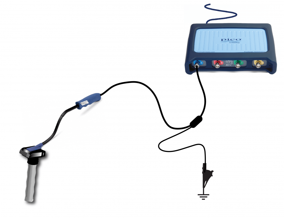
View connection guidance notes.
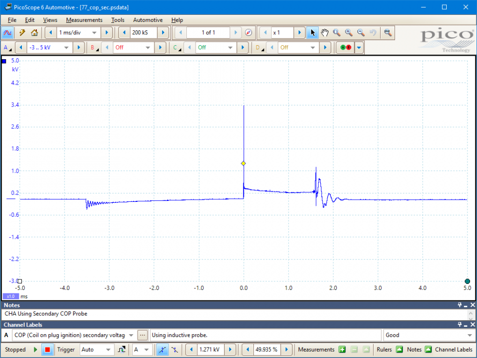
The ignition picture shown in the example waveform is a typical picture from an engine fitted with electronic ignition. The waveform has been taken from the coil on plug.
The secondary waveform shows the length of time for which the HT flows across the spark plug's electrode after the initial peak of voltage required to jump the plug gap. This time is referred to as either the 'burn time' or the 'spark duration'. In the illustration, the horizontal voltage line in the centre of the oscilloscope is at fairly constant voltage, but then drops sharply into what is referred to as the 'coil oscillation' period.
The coil oscillation period should display at least 4 peaks (including upper and lower). A loss of peaks indicates that the coil needs substituting. The period between the coil oscillation and the next 'drop down' is when the coil is at rest and there is no voltage in the coil's secondary circuit. The 'drop down' is referred to as the 'negative polarity peak', and produces a small oscillation in the opposite direction to the plug firing voltage. This is due to the initial switching on of the coil's primary current. The voltage within the coil is only released at the correct point of ignition when the HT spark ignites the air/fuel mixture.
The plug firing voltage is the voltage required to jump the gap at the plug's electrode, commonly known as the 'plug kV'. In this example the plug kV is 13.5 kV.
Go to the drop-down menu bar at the lower left corner of the Waveform Library window and select COP (Coil on plug ignition) secondary voltage.


The operation of the coil on plug is essentially the same as any other ignition system. Each coil has a low primary resistance, and steps up the primary system voltage to as much as 40,000 volts to produce a spark at the plug.
The only real difference between COP and other ignition systems is that each COP coil is mounted directly onto the spark plug, so the voltage goes directly to the plug electrodes without having to pass through a distributor or plug leads. This direct connection method delivers the strongest spark possible and improves the durability of the ignition system.
Using individual coils for each spark plug also means the coils have more time between each firing. Increasing the "coil saturation" time (the time the voltage to the coil is on to build up its magnetic field) increases the coil output voltage at high rpm when misfire is most likely to occur.
GT077-EN
Disclaimer
This help topic is subject to changes without notification. The information within is carefully checked and considered to be correct. This information is an example of our investigations and findings and is not a definitive procedure.
Pico Technology accepts no responsibility for inaccuracies. Each vehicle may be different and require unique test
settings.
We know that our PicoScope users are clever and creative and we’d love to receive your ideas for improvement on this test. Click the Add comment button to leave your feedback.
MikeW
February 08 2019
Hello Steven, firstly thank’s for the feedback. From your description it sounds like the system you have falls between two different guided tests. I’m sure the info you require can be found in - Ignition - COP 4-wire trigger and feedback, and in - Ignition - COP secondary HT extension lead. Sounds like you don’t need the extension lead only the capacitive pick-up. (please read the safety warning). Waveforms for secondary and primary ignition should all be very similar, it’s only the switching/triggering that is different. you might like to log-in to our automotive forum, contact like minded tec’s. http://www.picoauto.com/support/
steven h zoll
February 07 2019
Working on a GM V8 pushrod engine 6.0 liter. This engine uses a four wire primary, one coil per cylinder with a short HT wire to the plug. Will a capacitive pick up at the plug wire give me a usable waveform? I think that it will, but your automotive test guidance does not address this ignition setup . Are the actual waveforms themselves pretty much the same amongst the all the ignition systems? Thanks for your help.


