PicoScope 7 Automotive
Available for Windows, Mac, and Linux, the next evolution of our diagnostic scope software is now available.
Automotive guided tests
Library of examples on how to perform tests when using PicoScope.

Training
Our collection of training videos, articles, guides and information on training courses.

Waveform library
The Waveform Library is a global database of waveforms uploaded by PicoScope users.

Case studies
Real-life case studies show how the professionals use PicoScope to diagnose vehicle faults.

A to Z of PicoScope
Detailed description of various PicoScope software and hardware features.

Videos
Training resources and demonstrations on PicoScope and the Automotive Diagnostics Kit.

Newsletter
Archive of our monthly Automotive Newsletters.

Documentation
Download manuals, brochures, posters, and training materials.

Reviews and awards
Accolades for the preferred diagnostic tool for service centers and vehicle manufacturers.


20 A / 60 A DC (low amps) current clamp

10:1 Attenuator

Multimeter Probes
*At Pico we are always looking to improve our products. The tools used in this guided test may have been superseded and the products above are our latest versions used to diagnose the fault documented in this case study.
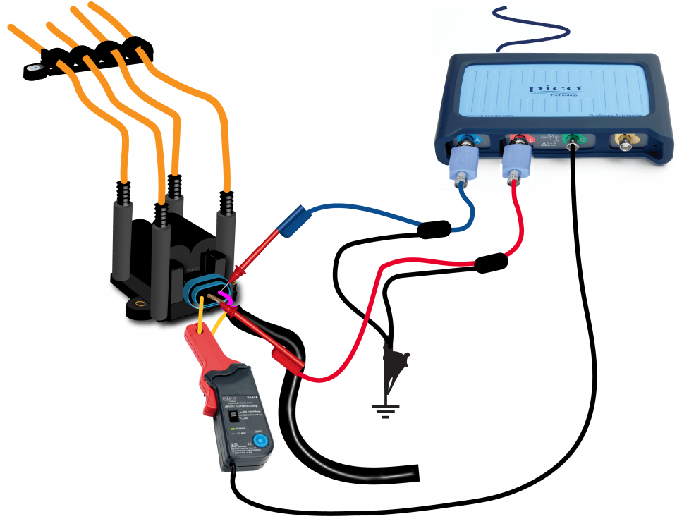
The purpose of this test is to examine the primary driver voltages and the current draw from a DIS coil pack.
WARNING
This test involves measuring a potentially hazardous voltage.
Please ensure you follow manufacturers' safety instructions and working practices and ensure the rated voltage for all accessories you are using meets or exceeds the expected voltage.
View connection guidance notes.
Note
If you are using a 20:1 attenuator please adjust the Probe settings for the relevant channel. These settings can be found under the Channel Options button, then: Probe > 20:1 Attenuator.
The orientation of the current clamp relative to the wire will determine whether it has a positive or negative output. If a live waveform does not appear on your screen, or appears to be inverted, try reversing the orientation of the clamp.

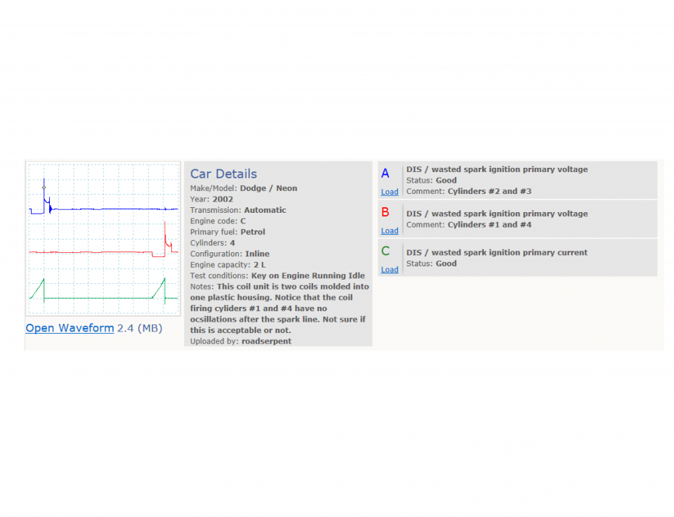
The waveform shows the driver voltages for both windings in the ignition coil. It also shows the current drawn during both driver events, allowing you to see if both coils are drawing the same amount of current during the operating cycle.
Go to the drop-down menu bar at the lower left corner of the Waveform Library window and select, DIS / wasted spark ignition primary voltage

DIS has major advantages over the distributor-based ignition system. These advantages include an absence of rotating high-voltage distribution components, and far lower levels of electromagnetic interference.
DIS is fitted only to vehicles that have an even number of cylinders, such as 2, 4, 6 or 8. This is because two cylinders are connected to one coil, which can send a spark to both cylinders at the same time. This system is commonly known as a wasted spark system. The two spark plugs are arranged so that one is fired on the power stroke of the engine and the other on the exhaust stroke of the opposing cylinder, offset by 360 degrees. After a complete rotation of the engine the two cylinders are now on the opposing strokes and the two spark plugs fire again but with opposite roles.
On a four-cylinder engine, there are two coils with individual drivers that tend to operate cylinders 1 and 4, and 2 and 3. This means there is a dual spark every 180 degrees, with one of those sparks wasted on an exhaust stroke of the opposing cylinder which is firing on the power stroke.
GT395
Disclaimer
This help topic is subject to changes without notification. The information within is carefully checked and considered to be correct. This information is an example of our investigations and findings and is not a definitive procedure.
Pico Technology accepts no responsibility for inaccuracies. Each vehicle may be different and require unique test
settings.
We know that our PicoScope users are clever and creative and we’d love to receive your ideas for improvement on this test. Click the Add comment button to leave your feedback.