PicoScope 7 Automotive
Available for Windows, Mac, and Linux, the next evolution of our diagnostic scope software is now available.
Automotive guided tests
Library of examples on how to perform tests when using PicoScope.

Training
Our collection of training videos, articles, guides and information on training courses.

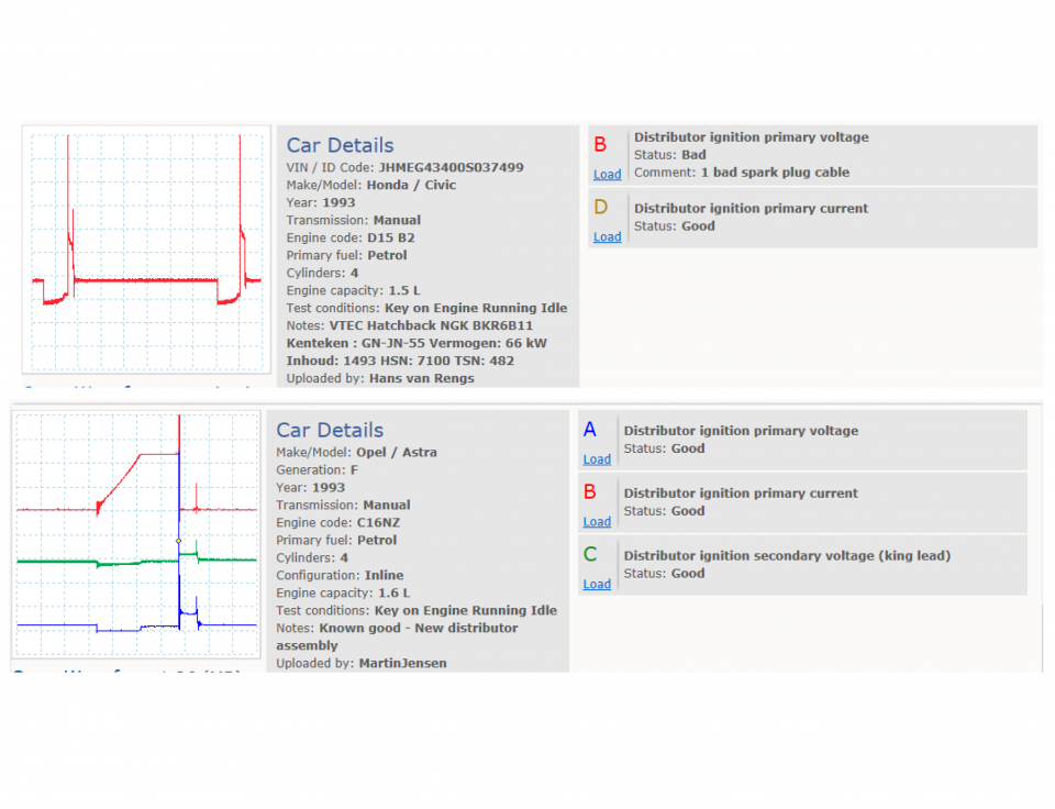
Waveform library
The Waveform Library is a global database of waveforms uploaded by PicoScope users.

Case studies
Real-life case studies show how the professionals use PicoScope to diagnose vehicle faults.

A to Z of PicoScope
Detailed description of various PicoScope software and hardware features.

Videos
Training resources and demonstrations on PicoScope and the Automotive Diagnostics Kit.

Newsletter
Archive of our monthly Automotive Newsletters.

Documentation
Download manuals, brochures, posters, and training materials.

Reviews and awards
Accolades for the preferred diagnostic tool for service centers and vehicle manufacturers.


10:1 Attenuator

Multimeter Probes
*At Pico we are always looking to improve our products. The tools used in this guided test may have been superseded and the products above are our latest versions used to diagnose the fault documented in this case study.
The purpose of this test is to examine primary ignition voltage on an external coil type ignition system.
WARNING
This test involves measuring a potentially hazardous voltage.
Please ensure you follow manufacturers' safety instructions and working practices and ensure the rated voltage for all accessories you are using meets or exceeds the expected voltage.
To avoid possible damage to your scope, you may need to use an attenuator for this test.
Scopes with a 200 V range, such as PicoScope 4x25 models, do not need an attenuator for this test.
All other PicoScope Automotive models need an attenuator on the channel input. You can use either a 10:1 or a 20:1 attenuator provided that you adjust the PicoScope software accordingly. Select from the appropriate Channel Options menu:
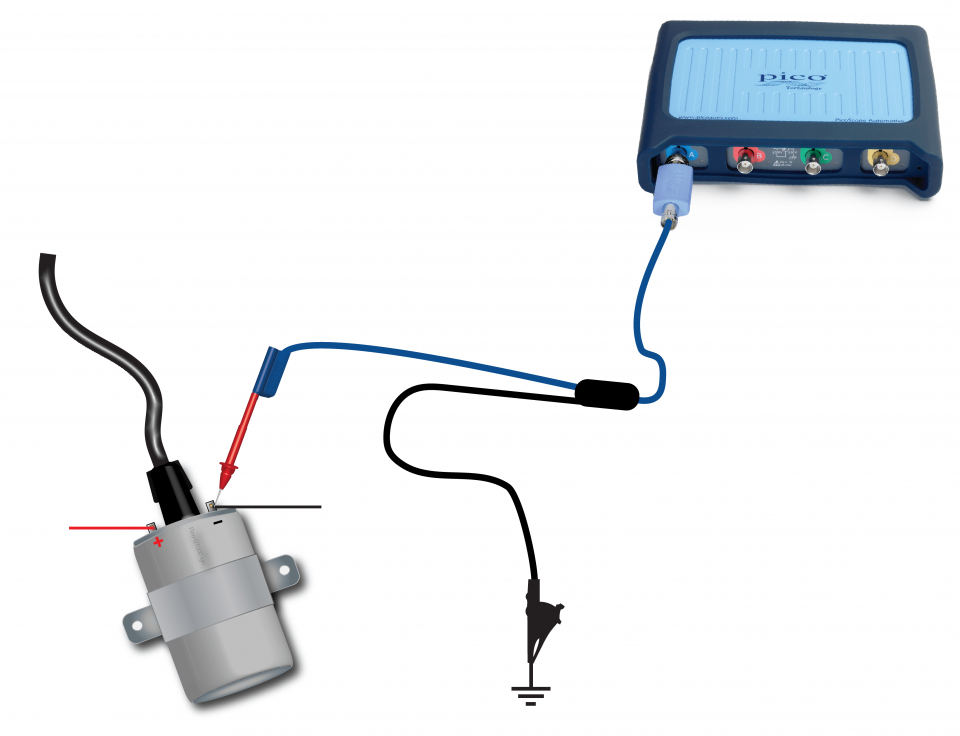
View connection guidance notes.
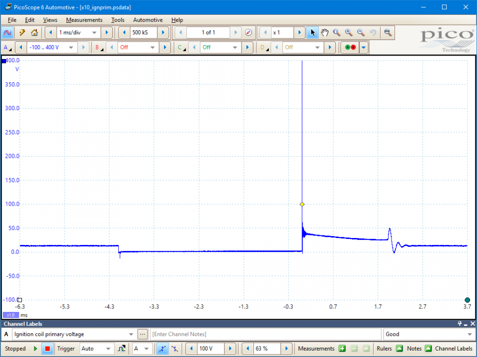
This known good waveform has the following characteristics:
Go to the drop-down menu bar at the lower left corner of the Waveform Library window and select, Distributor ignition primary voltage

General principles
All (inductive) spark ignition systems use one or more ignition coils. The coils act as both an accumulator, to store energy, and a step-up transformer, to generate the high voltages necessary to produce an electrical spark within a combustion chamber.
An ignition coil consists of a primary coil and a secondary coil, wound around each other in close proximity. The secondary coil has a high ratio of windings to the primary coil. This arrangement creates conditions of high mutual inductance, meaning changes in the magnetic field in the primary coil will produce changes in voltage in the secondary coil.
The primary coil is connected within the primary circuit. When current flows in the primary circuit, energy builds within the coil’s magnetic field. If the current is quickly removed, the magnetic field rapidly collapses and induces a high voltage in the secondary coil. The high voltage is delivered to a spark plug via a secondary circuit.
The time the coil takes to reach its maximum magnetic field strength (its saturation time) depends on the peak primary circuit current, which, in turn, depends on the total primary circuit resistance and the primary coil's tendency to resist the build-up of current (its inductance).
The period during which the current flows within the primary circuit is known as the dwell period (or the dwell angle, if referenced to the angle of crankshaft rotation). The dwell period must be sufficiently long (at all engine speeds) to allow the primary coil to reach maximum magnetic field strength (i.e. to saturate).
The peak current and dwell period are Key Performance Indicators (KPIs) for primary circuit control. Please refer to manufacturer’s technical information to find the specifications for your vehicle.
Distributor ignition
Distributor based ignition systems use a single ignition coil.
The switching of the primary circuit can be controlled using one of two mechanisms:
Most mechanically triggered primary circuits require a ballast resistor to regulate the current flow, whereas a transistorised system is able to vary the current more freely.
A component rotating internally within the distributor, the rotor, directs the secondary voltages to each of the engine’s spark plugs, in their firing order, as it passes peripheral electrodes connected to the spark plug leads.
Primary voltage diagnostics
GT386
Disclaimer
This help topic is subject to changes without notification. The information within is carefully checked and considered to be correct. This information is an example of our investigations and findings and is not a definitive procedure.
Pico Technology accepts no responsibility for inaccuracies. Each vehicle may be different and require unique test
settings.
We know that our PicoScope users are clever and creative and we’d love to receive your ideas for improvement on this test. Click the Add comment button to leave your feedback.


