PicoScope 7 Automotive
Available for Windows, Mac, and Linux, the next evolution of our diagnostic scope software is now available.
Automotive guided tests
Library of examples on how to perform tests when using PicoScope.

Training
Our collection of training videos, articles, guides and information on training courses.

Waveform library
The Waveform Library is a global database of waveforms uploaded by PicoScope users.

Case studies
Real-life case studies show how the professionals use PicoScope to diagnose vehicle faults.

A to Z of PicoScope
Detailed description of various PicoScope software and hardware features.

Videos
Training resources and demonstrations on PicoScope and the Automotive Diagnostics Kit.

Newsletter
Archive of our monthly Automotive Newsletters.

Documentation
Download manuals, brochures, posters, and training materials.

Reviews and awards
Accolades for the preferred diagnostic tool for service centers and vehicle manufacturers.


PicoScope Battery Clip
*At Pico we are always looking to improve our products. The tool used in this guided test may have been superseded and the product above is our latest version used to diagnose the fault documented in this case study.
The purpose of this test is to examine the operation of the multi-coil-on-plug ignition primary voltage and dual driver signals.
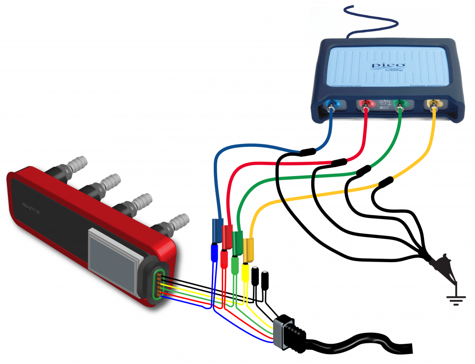
View connection guidance notes.
The example waveform is from the coil-on-plug unit on the Vectra Z22SE engine.
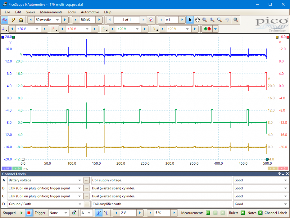
The coil supply is at the battery or charging voltage of 12 volts or more. In this example, the voltage is about 14.0 volts. When the coil's primary circuit is switched on, the voltage drops slightly, and as the current in the circuit increases to the target of 10 amps, the voltage drops accordingly. The final voltage is about 13 volts - 1 volt lower than the original voltage.
The low-tension (LT) signal switches between zero volts and about 5 volts. When the trigger signal goes high, it causes the coil to switch on. As the voltage returns to zero, the current in the coil's primary winding switches off, the magnetic flux surrounding the winding collapses, this induces a voltage in the secondary and the coil's HT is fired. The switch-on (zero rising to 5 volts) and switch-off (5 volts to zero) points are determined by the vehicle's Electronic Control Module (ECM). This interval between these events is called either the dwell period or the saturation time. The dwell period on an engine with electronic ignition is controlled by the current-limiting circuit in the amplifier or ECM.
The voltage when the coil is disconnected is of course zero volts, rising to about 0.1 volts when the coil is energized. If the circuit is suffering from a poor earth connection, this voltage will be higher; so the lower the voltage, the better the earth connection.

The operation of the coil-on-plug unit is essentially the same as any other ignition system.
The distributorless ignition systems are fitted only to vehicles that have an even number of cylinders such as 2, 4, 6 or 8. The reason for this is that two cylinders are connected to one coil that produces a spark for both cylinders at the same time. This system is known as a wasted spark system. The two spark plugs are arranged so that one is fired on the power stroke of the engine and the other on the exhaust stroke of the opposing cylinder, offset by 360 degrees. After a complete rotation of the engine the two cylinders are now on the opposing strokes and the two spark plugs fire again but with the opposite roles .
On a 4 cylinder engine, there are 2 coils with individual drivers and these tend to operate cylinders 1 and 4, and 2 and 3. This means there is a dual spark every 180 degrees with one of those sparks wasted on an exhaust stroke of the opposing cylinder which is firing on the power stroke.
The only real difference between COP and other ignition systems is that each COP coil is mounted directly on the spark plug, so the voltage goes directly to the plug electrodes without having to pass through a distributor or plug leads. This direct connection method delivers a stronger spark and makes the ignition system more reliable.
The switch-on (zero rising to 5 volts) and switch-off (5 volts to zero) points of the coil are determined by the vehicle's Electronic Control Module (ECM). The time between these points is called either the dwell period or the coil saturation time. The dwell period on an engine with electronic ignition is controlled by the current-limiting circuit in the amplifier or ECM.
Historically, the supply voltage was present as soon as the ignition switch was turned to the 'on' position. Modern systems, however, do not provide a supply until the key is turned to the 'crank' position and the engine turns. A simple fault such as a non-functioning crank angle sensor may result in a loss of supply voltage, simply because the electronic control circuits do not recognize that the engine is rotating.
The earth connection is essential to the operation of any electrical circuit in an engine. As the current increases, so does the voltage drop on any given electrical circuit. An earth return circuit can only be tested while the circuit is under load, so simple continuity testing to earth with a multimeter is inaccurate. As the primary coil circuit is only closed during the dwell period, the voltage drop should be monitored during this period. The voltage ramp on the earth signal should not exceed 0.5 volts. The flatter the waveform the better: a waveform with virtually no rise shows that the amplifier or module has a perfect earth. If the ramp is too high, the earth connections need to be investigated to identify the offending connection.
GT176
Disclaimer
This help topic is subject to changes without notification. The information within is carefully checked and considered to be correct. This information is an example of our investigations and findings and is not a definitive procedure.
Pico Technology accepts no responsibility for inaccuracies. Each vehicle may be different and require unique test
settings.
We know that our PicoScope users are clever and creative and we’d love to receive your ideas for improvement on this test. Click the Add comment button to leave your feedback.


