PicoScope 7 Automotive
Available for Windows, Mac, and Linux, the next evolution of our diagnostic scope software is now available.

Back-pinning Probe Set

Flexible Back-pinning Probe

Small Crocodile/Gator Clips

PicoScope Sprung Hook Probe

10:1 Attenuator

Premium Test Lead: BNC to 4 mm, 3 m

Premium Test Leads: Set of four leads 3 m (TA125 - TA128)
*At Pico we are always looking to improve our products. The tools used in this guided test may have been superseded and the products above are our latest versions used to diagnose the fault documented in this case study.
Note: This test refers to a 20:1 attenuator. If you are using a 10:1 attenuator please adjust the Probe settings for the relevant channel. These settings can be found under the Channel Options button, then: Probe > 10:1 Attenuator.
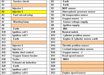
Plug a 20:1 attenuator into Channel A of the scope. Plug a BNC test lead into the attenuator. Place a small black clip on the lead end with a black moulding (negative) and a Back-pinning Probe onto the end with a red moulding (positive). Place the small black clip on to the motorcycle frame or battery negative, as illustrated in Figure 1. Check the manufacturer's pin data for the fuel injection Electronic Control Module (ECM) fuel injector connection terminal. Back-probe the correct multiplug pin with the Back-pinning Probe as in Figure 2. Ensure that a good connection is made through to the wire or terminal and the probe has pierced through the wire and plug insulation.
With the example waveform displayed on the screen you can now hit the space bar to start looking at live readings.
The injector is an electromechanical device which is fed by a 12 volt supply. The voltage is only present when the engine is cranking or running, as it is controlled by a tachometric relay.
The injector has a constant-voltage supply while the engine is running and the earth path is switched via the ECM. The result can be seen in the example waveform. When the earth is removed, a voltage is induced into the injector and a spike approaching 50 volts is recorded.
Multi-point injection may be either sequential or simultaneous. A simultaneous system fires all 4 injectors at the same time, with each cylinder receiving 2 injection pulses per cycle (720 crankshaft rotation). A sequential system, which tends to be used on motorcycle engines, receives just 1 injection pulse per cycle, and this is timed to coincide with the opening of the inlet valves.
The injector is supplied with fuel from a common fuel rail, or two in the case of a V engine.
The length of time that the injectors are held open for depends on the input signals seen by the engine management ECM from its various engine sensors.
These input signals include:
The held-open time, or injector duration, varies to compensate for cold engine starting and warm-up periods. It begins with a long duration that decreases as the engine warms to operating temperature. The duration also lengthens under acceleration and contracts under light load conditions.
With sequential injection systems, the injectors fire once per cycle. The injector wiring with sequential injection has a common supply to each injector and has a separate earth path going back to the motorcycle's ECM. This individual firing allows the system, when used in conjunction with a phase sensor, to deliver the fuel when the inlet valve/valves are open and the incoming air helps to atomise the fuel.
If a fault is suspected, ensure that the durations are comparable between all sequentially fired injectors when the engine has achieved full operating temperature, and that the 'switched on and off' sections of the waveform are switching cleanly and have vertical lines on the waveform. Any sloping of the trace in these areas shows insufficient switching speed.
Our test vehicle was a Honda motorbike. Below is the ECM multiplug pin data. Pin data is manufacturer- and model-specific and this data is shown for illustration purposes only.


AT398-1
Disclaimer
This help topic is subject to changes without notification. The information within is carefully checked and considered to be correct. This information is an example of our investigations and findings and is not a definitive procedure.
Pico Technology accepts no responsibility for inaccuracies. Each vehicle may be different and require unique test
settings.
We know that our PicoScope users are clever and creative and we’d love to receive your ideas for improvement on this test. Click the Add comment button to leave your feedback.