PicoScope 7 Automotive
Available for Windows, Mac, and Linux, the next evolution of our diagnostic scope software is now available.

20 A / 60 A DC (low amps) current clamp
*At Pico we are always looking to improve our products. The tool used in this guided test may have been superseded and the product above is our latest version used to diagnose the fault documented in this case study.
Plug the low-amp current clamp into Channel A of the scope. Switch the clamp to the 20 A range if applicable and zero the clamp. Check the manufacturer's pin data for the fuel injection Electronic Control Module (ECM) fuel injector connection terminal. Place the current clamp around the correct wire as in Figure 1.
With the example waveform displayed on the screen you can now hit the space bar to start looking at live readings.
The waveform 2 shows that the injector current pulse consists of two stages. During the first stage, the force developed by the solenoid is not enough to open the valve. This condition lasts for about 1.5 ms. At this point valve opens, changing the inductance of the solenoid and so causing a dip in the waveform before the current rises again. The current then levels off as the solenoid coil becomes magnetically saturated, and is then switched off by the motorcycle's Electronic Control Module (ECM). This injector 'open time' depends on the parameters listed in the Technical Information section below.
With this in mind it can be seen that the amount of time that the injector is held open is not necessarily the same as the complete duration of the pulse (about 6 ms). It is not, however, possible to calculate the time taken for the injector's spring to fully close the valve and cut off the fuel flow. This test is ideal for identifying an injector with an unacceptably slow solenoid reaction time. Such an injector would not deliver the required amount of fuel and the cylinder in question would run lean.
The multi-point injector is an electromechanical device that is fed by a 12 volt supply from either the fuel injection relay or the Electronic Control Module (ECM).
The injector is supplied with fuel from a common fuel rail. The length of time for which the injector is held open depends on the input signals received by the engine management ECM from its various engine sensors. These inputs include:-
The held-open time, or injector duration, varies to compensate for cold engine starting and warm-up periods. It begins with a long duration that decreases as the engine warms to operating temperature. The duration also lengthens under acceleration and shortens under light load conditions.
The injectors fire once per cycle (720° of crank angle or two revolutions). Sequential injection has a common supply to all the injectors and a separate, switched, earth path to each injector. This individual firing allows the system, when used in conjunction with a phase sensor, to deliver the fuel when the inlet valve is open and the incoming air helps to atomise the fuel.
Observe the individual injector current waveforms and ensure that all the waveforms appear similar. A slower than expected opening time may be due to increased electrical resistance in the injector's solenoid coil. This can be confirmed by removing the electrical connector to the injector and measuring the coil's resistance with a multimeter. This resistance reading will vary between motorcycle manufacturers but should be similar to the other injectors in the same engine. If the resistance is found to be higher, the injector should be replaced by one with the correct resistance and comparable flow rates. An injector with a slow reaction time will cause the affected cylinder to run lean, causing lower performance and possibly serious engine damage.
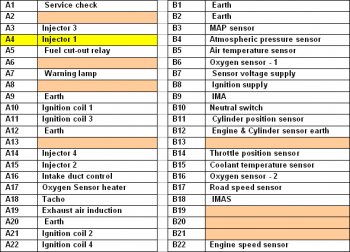
Our test vehicle was a Honda motorbike. Below is the ECM multiplug pin data. Pin data is manufacturer- and model-specific and this data is shown for illustration purposes only.


AT114-4
Disclaimer
This help topic is subject to changes without notification. The information within is carefully checked and considered to be correct. This information is an example of our investigations and findings and is not a definitive procedure.
Pico Technology accepts no responsibility for inaccuracies. Each vehicle may be different and require unique test
settings.
We know that our PicoScope users are clever and creative and we’d love to receive your ideas for improvement on this test. Click the Add comment button to leave your feedback.