PicoScope 7 Automotive
Available for Windows, Mac, and Linux, the next evolution of our diagnostic scope software is now available.
Automotive guided tests
Library of examples on how to perform tests when using PicoScope.

Training
Our collection of training videos, articles, guides and information on training courses.

Waveform library
The Waveform Library is a global database of waveforms uploaded by PicoScope users.

Case studies
Real-life case studies show how the professionals use PicoScope to diagnose vehicle faults.

A to Z of PicoScope
Detailed description of various PicoScope software and hardware features.

Videos
Training resources and demonstrations on PicoScope and the Automotive Diagnostics Kit.

Newsletter
Archive of our monthly Automotive Newsletters.

Documentation
Download manuals, brochures, posters, and training materials.

Reviews and awards
Accolades for the preferred diagnostic tool for service centers and vehicle manufacturers.


Premium Test Leads: Set of four leads 3 m (TA125 - TA128)

Premium Test Lead: BNC to 4 mm, 3 m

Multimeter Probes
*At Pico we are always looking to improve our products. The tools used in this guided test may have been superseded and the products above are our latest versions used to diagnose the fault documented in this case study.
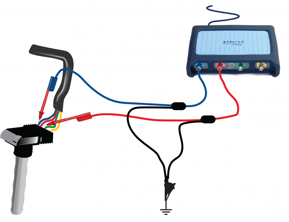
The purpose of this test is to examine the individual signals in a 4-wire COP unit to identify the signals and verify correct operation.
WARNING
This test involves measuring a potentially hazardous voltage.
Please ensure you follow manufacturers' safety instructions and working practices and ensure the rated voltage for all accessories you are using meets or exceeds the expected voltage.
View connection guidance notes.
Minimize the help page. You will see that PicoScope has displayed an example waveform and is preset to capture your waveform.
Use the Waveform Buffer, Zoom and Measurements tools to examine your waveform.
Note
This test is for a 4-wire COP with a feedback signal to the ECU. Some 4-wire COPs have two ground pins and no feedback signal, these should be tested as a 3-wire COP please see 3-Wire COP Test.

The Example Waveform is showing the trigger signals from the coil selected on Channel A and the common feedback signal on Channel B.
Channel A. Trigger Signal.
The trigger signal rises from 0 V to about 4 V at coil switch-on and then returns to 0 V at coil switch-off. The time between these events is the dwell period or coil saturation time, determined by the Engine Control Module (ECM) or ignition amplifier.
Channel B. Feedback signal.
The feedback signal tells the ECM that ignition has occurred. The feedback signal on this engine is common to all four cylinders, so there are four feedback pulses for every engine cycle.
Go to the drop-down menu bar in the lower left corner of the Waveform Library window and select COP feedback signals.


A 4-wire COP has the following connections, pin numbers may vary depending on the type of coil.
In addition to the trigger and feedback signals shown in the waveform above, it is sometimes useful to monitor the positive supply voltage and current and the ground voltage. For instructions on checking the supply and ground/earth pins, see the 3-wire COP test.
Positive supply voltage. This should be close to battery voltage. If it is low or absent then the ignition system is not receiving enough power and the coil will not function.
Ground. A small pulse will be seen on this signal during ignition as the coil draws current from the battery, but the pulse height should not exceed a few hundred mV. A larger voltage indicates too much resistance in the ground wiring, which could cause an ignition fault.
GT198-4
Disclaimer
This help topic is subject to changes without notification. The information within is carefully checked and considered to be correct. This information is an example of our investigations and findings and is not a definitive procedure.
Pico Technology accepts no responsibility for inaccuracies. Each vehicle may be different and require unique test
settings.
We know that our PicoScope users are clever and creative and we’d love to receive your ideas for improvement on this test. Click the Add comment button to leave your feedback.