PicoScope 7 Automotive
Available for Windows, Mac, and Linux, the next evolution of our diagnostic scope software is now available.
Automotive guided tests
Library of examples on how to perform tests when using PicoScope.

Training
Our collection of training videos, articles, guides and information on training courses.

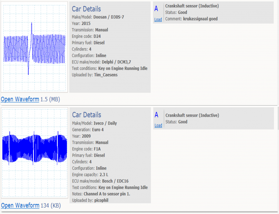
Waveform library
The Waveform Library is a global database of waveforms uploaded by PicoScope users.

Case studies
Real-life case studies show how the professionals use PicoScope to diagnose vehicle faults.

A to Z of PicoScope
Detailed description of various PicoScope software and hardware features.

Videos
Training resources and demonstrations on PicoScope and the Automotive Diagnostics Kit.

Newsletter
Archive of our monthly Automotive Newsletters.

Documentation
Download manuals, brochures, posters, and training materials.

Reviews and awards
Accolades for the preferred diagnostic tool for service centers and vehicle manufacturers.


Multimeter Probes

Back-pinning Probe Set

PicoScope Battery Clip

Premium Test Lead: BNC to 4 mm, 3 m
*At Pico we are always looking to improve our products. The tools used in this guided test may have been superseded and the products above are our latest versions used to diagnose the fault documented in this case study.
The purpose of this test is to evaluate a Crankshaft Position (CKP) sensor’s inductive, referenced, output voltage with the engine running.

View connection guidance notes.
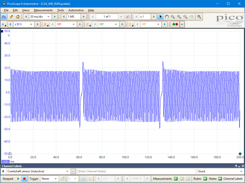
This known good waveform has the following characteristics:
Go to the drop-down menu bar at the lower left corner of the Waveform Library window and select Crankshaft sensor (Inductive).


An inductive Crankshaft Position (CKP) sensor provides an Engine Control Module (ECM) with its primary engine timing reference signal. The ECM uses the signal to calculate the engine speed and position for accurate injection and ignition control. The signal is also used to detect engine speed anomalies from misfires etc.
An inductive CKP sensor consists of a circuit with a wire coiled around a magnet. The sensor is accompanied by a pulse wheel, typically arranged about the flywheel circumference. The pulse wheel passes through and disturbs the sensor magnetic field inducing a circuit voltage. The induced voltage depends on engine speed: the faster the pulse wheel rotates, the greater the magnetic field disturbance.
When either the tooth or gap centres align with the sensor, there is an equal and opposite magnetic field disturbance and no voltage is induced. Conversely, as either a tooth leading or trailing edge aligns with the sensor, the magnetic field disturbance and induced voltage are greatest.
Positive voltage is produced when a tooth leading edge is closer than its trailing edge, and a negative voltage is produced in the opposite case.
The missing tooth on the pulse wheel provides the main timing reference mark. As the gap passes through the magnetic field, there is a period of reduced disturbance and voltage. Furthermore, the trailing and leading edge of the teeth that immediately precede and follow the gap are further apart, thus they produce a larger net magnetic field disturbance and induced voltage.
The CKP sensor signal is critical to ECM operation and it will not start or run an engine if the signal is missing or faulty. Therefore, the sensor can cause engine cranking but not starting or engine cutting out symptoms.
Possible faults are:
A two pin CKP sensor and ECM circuit can be arranged in two ways, with either:
Selection of component related Diagnostic Trouble Codes (DTCs):
P0016 Crankshaft Position - Camshaft Position Correlation Bank 1 Sensor A
P0017 Crankshaft Position - Camshaft Position Correlation Bank 1 Sensor B
P0018 Crankshaft Position - Camshaft Position Correlation Bank 2 Sensor A
P0019 Crankshaft Position - Camshaft Position Correlation Bank 2 Sensor B
P0315 Crankshaft Position - system variation values are not stored in the PCM memory
P0335 Crankshaft Position Sensor A Circuit Malfunction
P0336 Crankshaft Position Sensor A Circuit Range/Performance
P0337 Crankshaft Position Sensor A Circuit Low Input
P0338 Crankshaft Position Sensor A Circuit High Input
P0339 Crankshaft Position Sensor A Circuit Intermittent
P0385 Crankshaft Position Sensor B Circuit Malfunction
P0386 Crankshaft Position Sensor B Circuit Range/Performance
P0387 Crankshaft Position Sensor B Circuit Low Input
P0388 Crankshaft Position Sensor B Circuit High Input
P0389 Crankshaft Position Sensor B Circuit Intermittent
GT430-EN
Disclaimer
This help topic is subject to changes without notification. The information within is carefully checked and considered to be correct. This information is an example of our investigations and findings and is not a definitive procedure.
Pico Technology accepts no responsibility for inaccuracies. Each vehicle may be different and require unique test
settings.
We know that our PicoScope users are clever and creative and we’d love to receive your ideas for improvement on this test. Click the Add comment button to leave your feedback.


